Industrial solutions

Precision welding.
Built around your system.

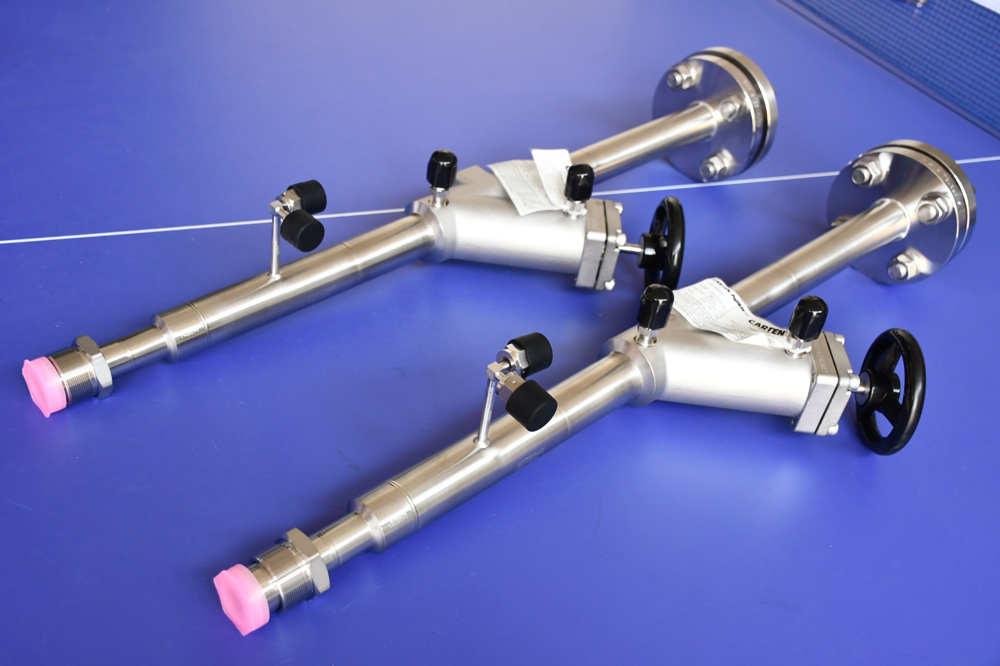
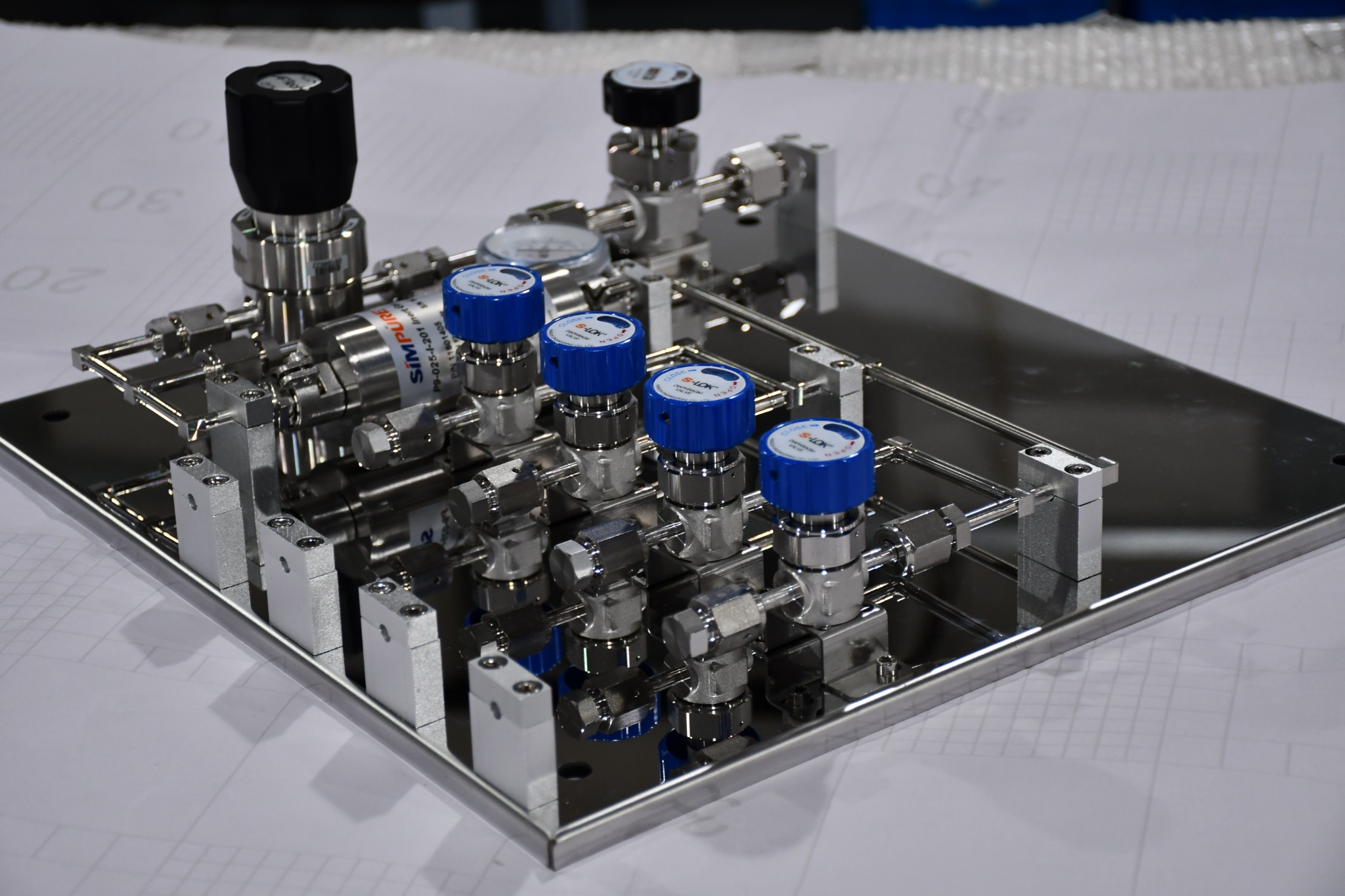
Orbital-welded assemblies, vacuum cooling products, and freeform bent and welded tubing for semiconductor equipment, research systems and industrial installations.

Vacuum components & welded piping

The joint. The circuit.
The geometry.

Start with the application: a precision tube joint, a vacuum cooling connection, or a custom route through a compact equipment layout.

Explore the three product areas below, then share your drawing, operating conditions and connection requirements with our team.

Discuss your application →
01 / PRECISION TUBE JOINING

Orbital-Welded Assemblies

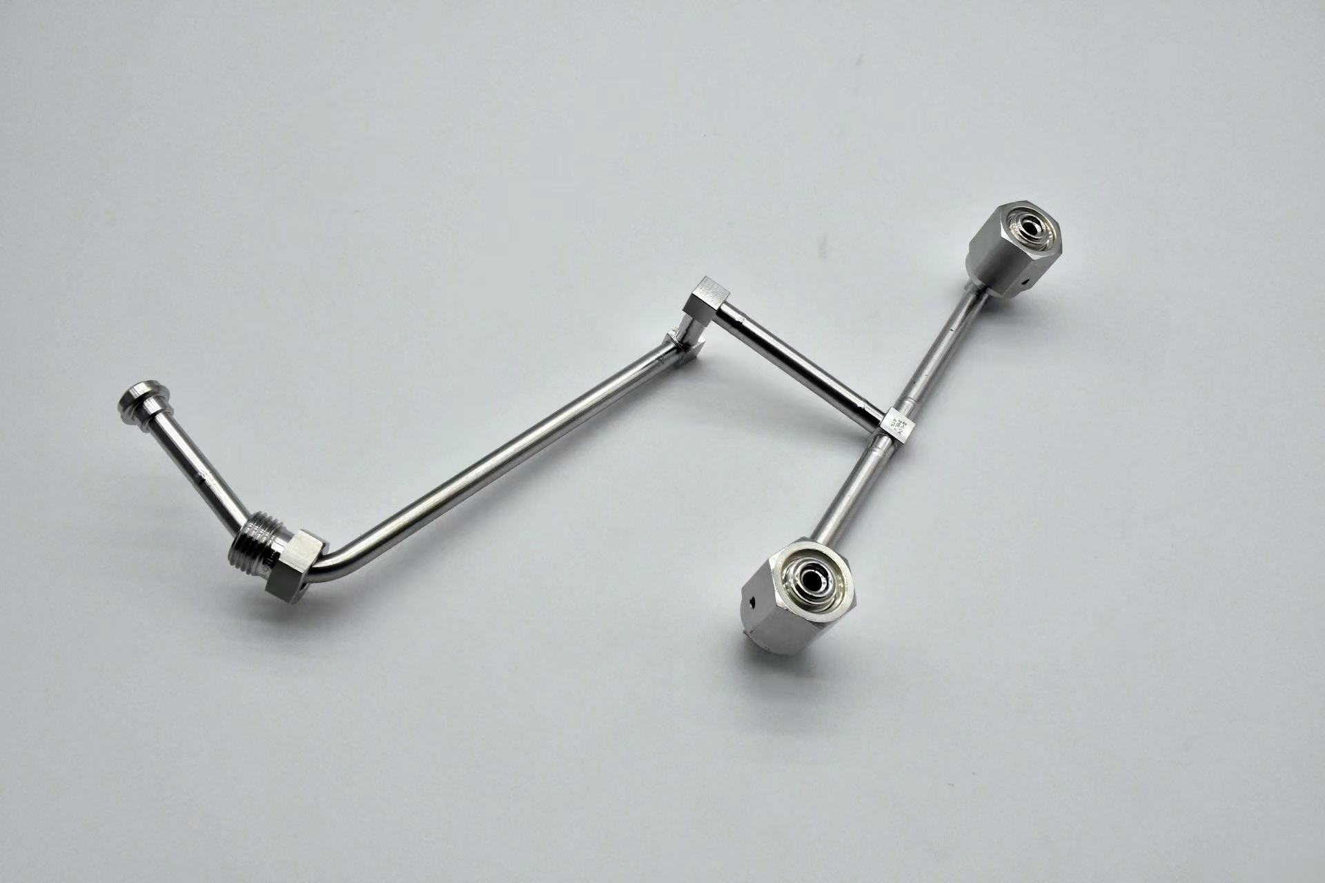
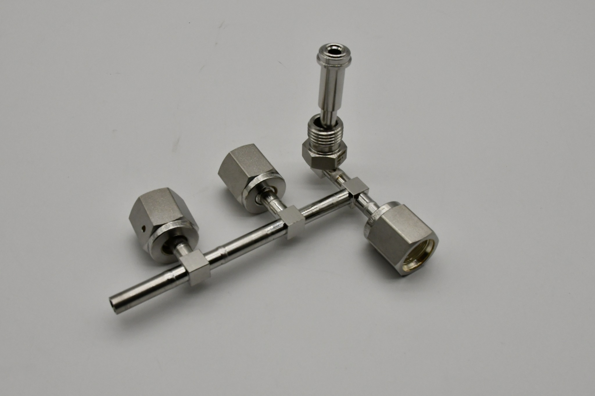
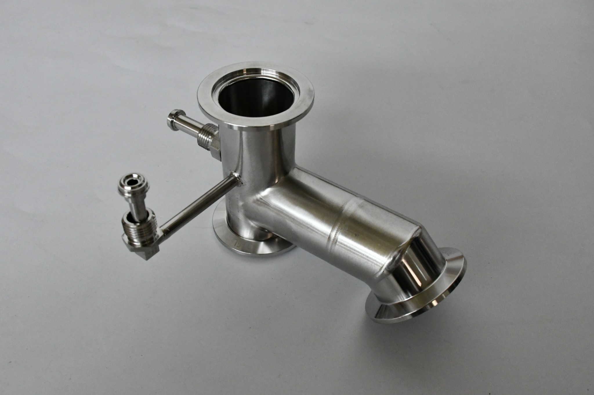
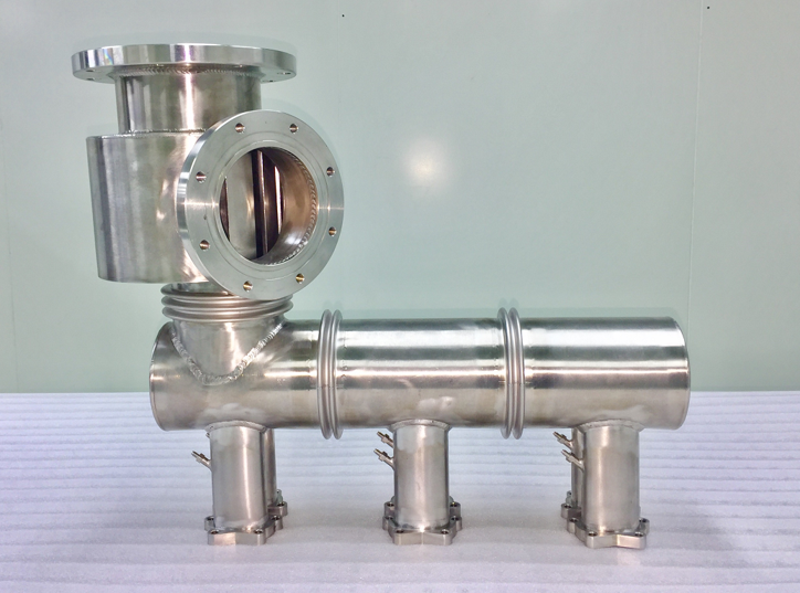
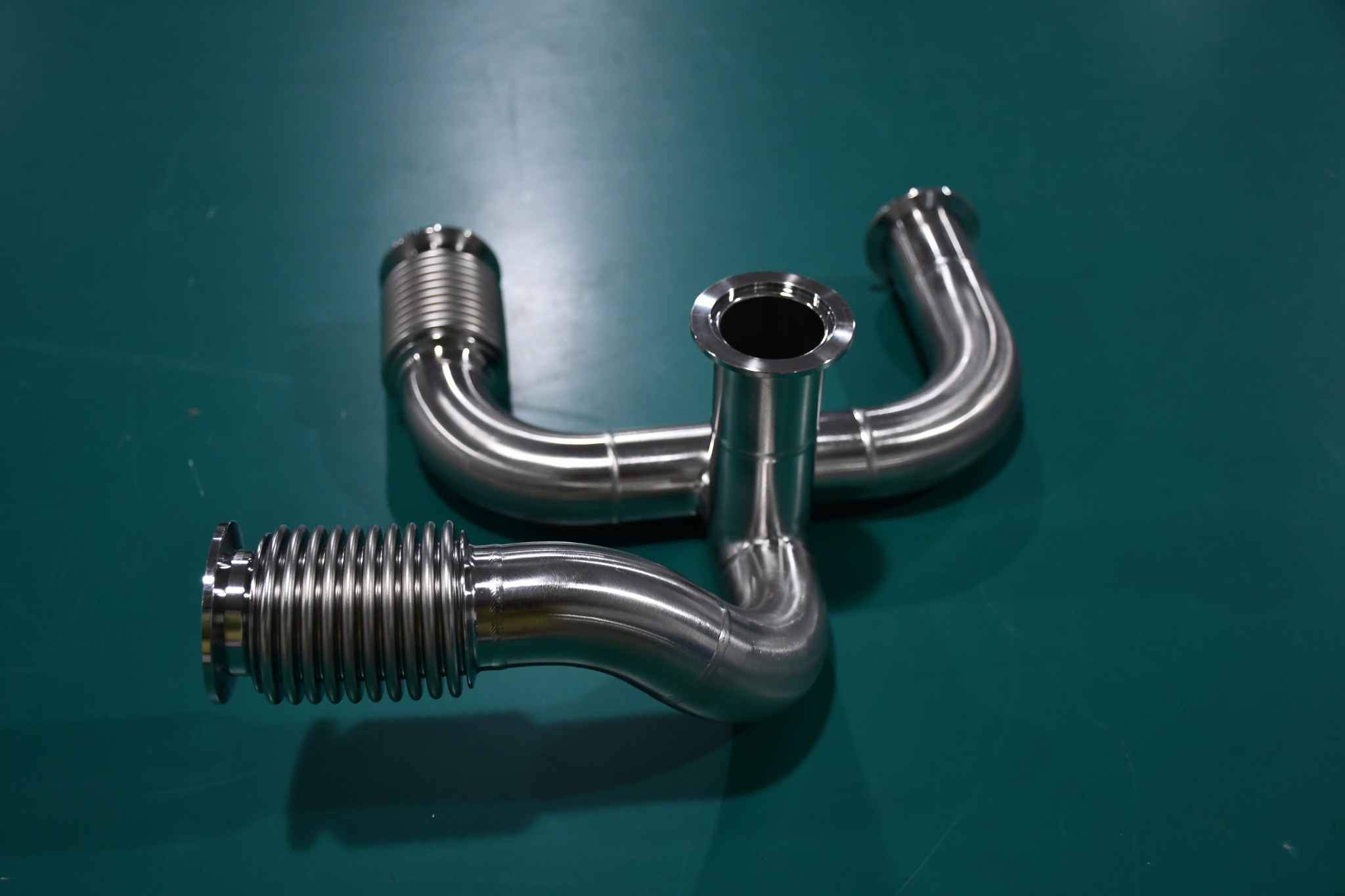
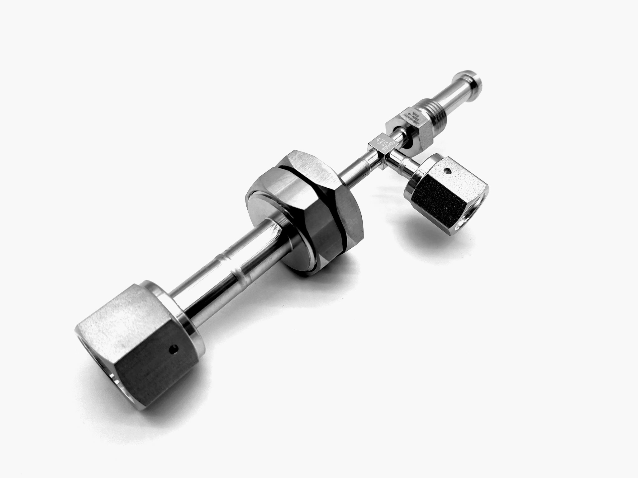
Tube and fitting assemblies with drawing-defined joints and connection layouts. Explore branch lines, flanged interfaces, manifolds and integrated piping assemblies in the supplied examples.

  • Straight and bent tube layouts with branches and mixed end connections
  • Specify material, tube dimensions, joint geometry and cleanliness requirements
  • Define weld inspection, leak testing and system integration requirements
Discuss this product area →
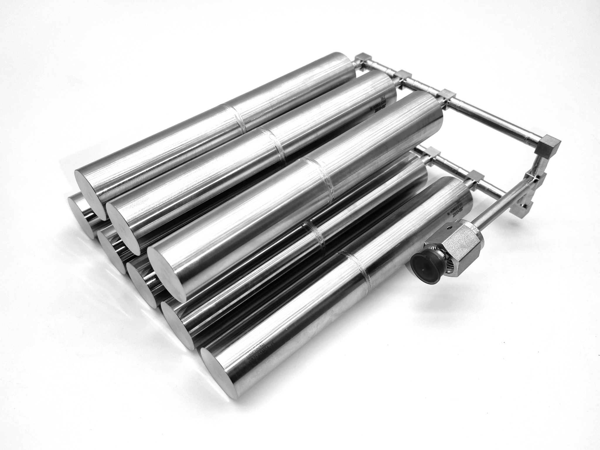
Tube and branch fitting assembly

Click a photo to view it at full size. Final specifications are confirmed against the selected drawing.
02 / VACUUM COOLING PRODUCTS

Vacuum Cooling Products

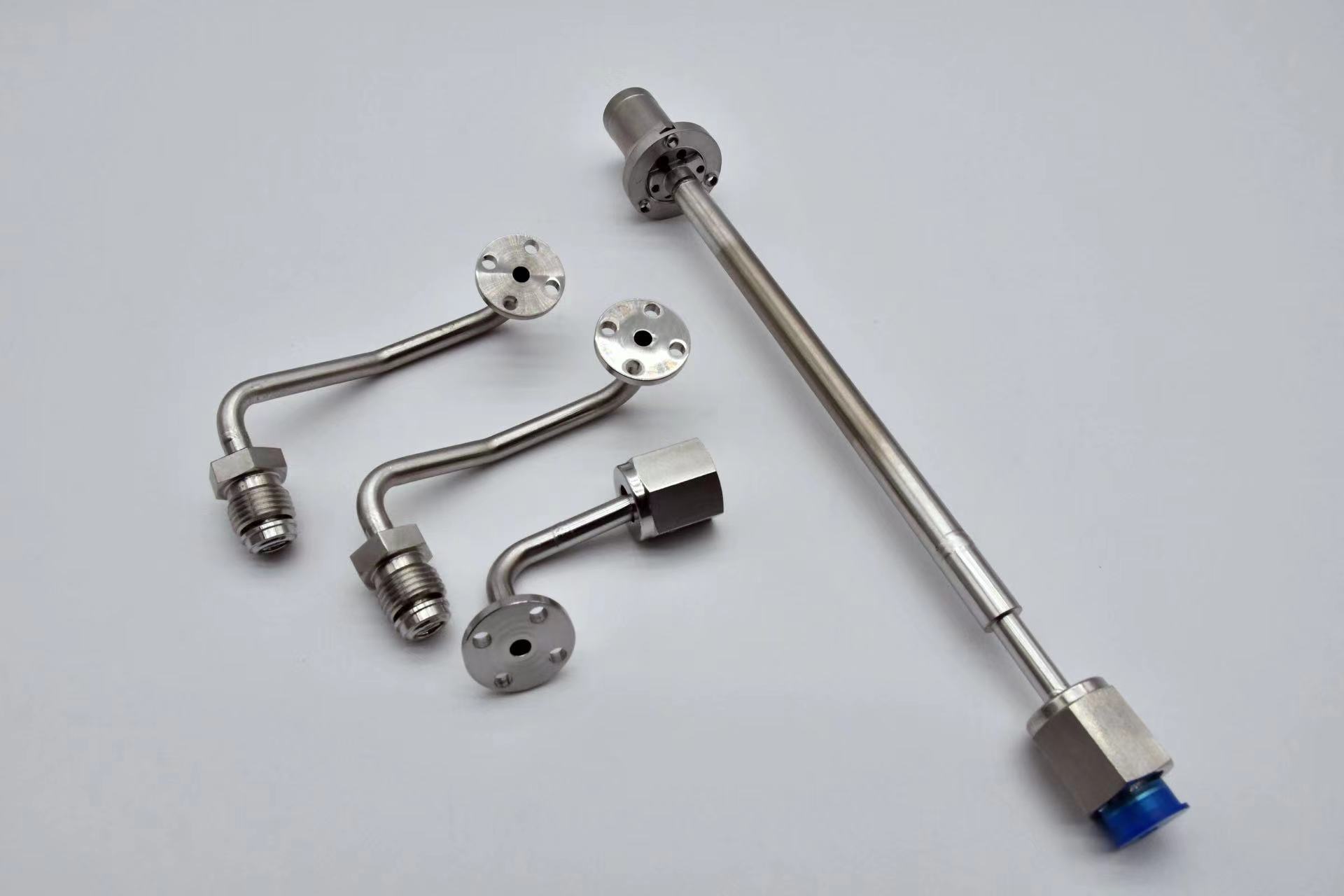
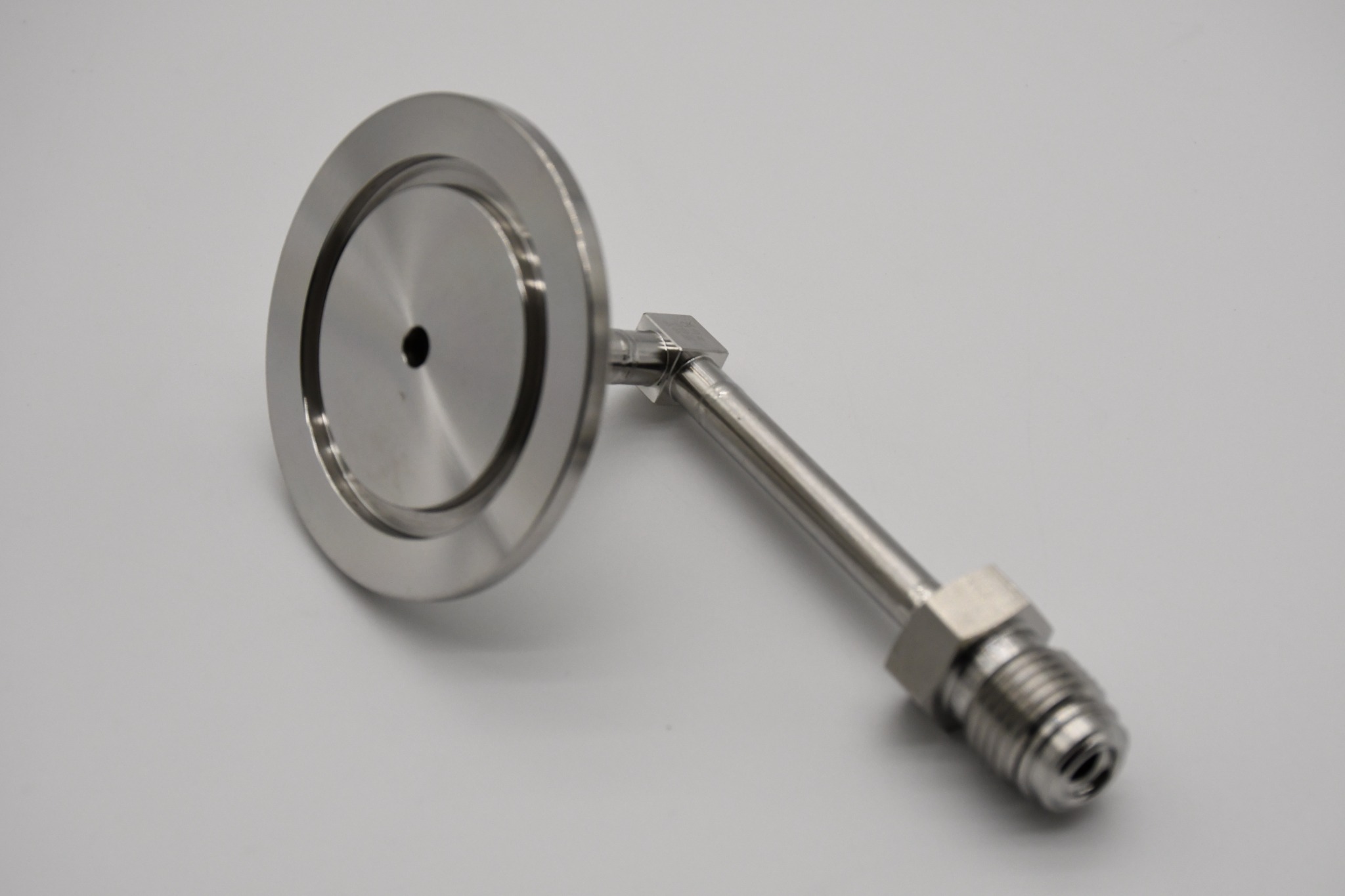
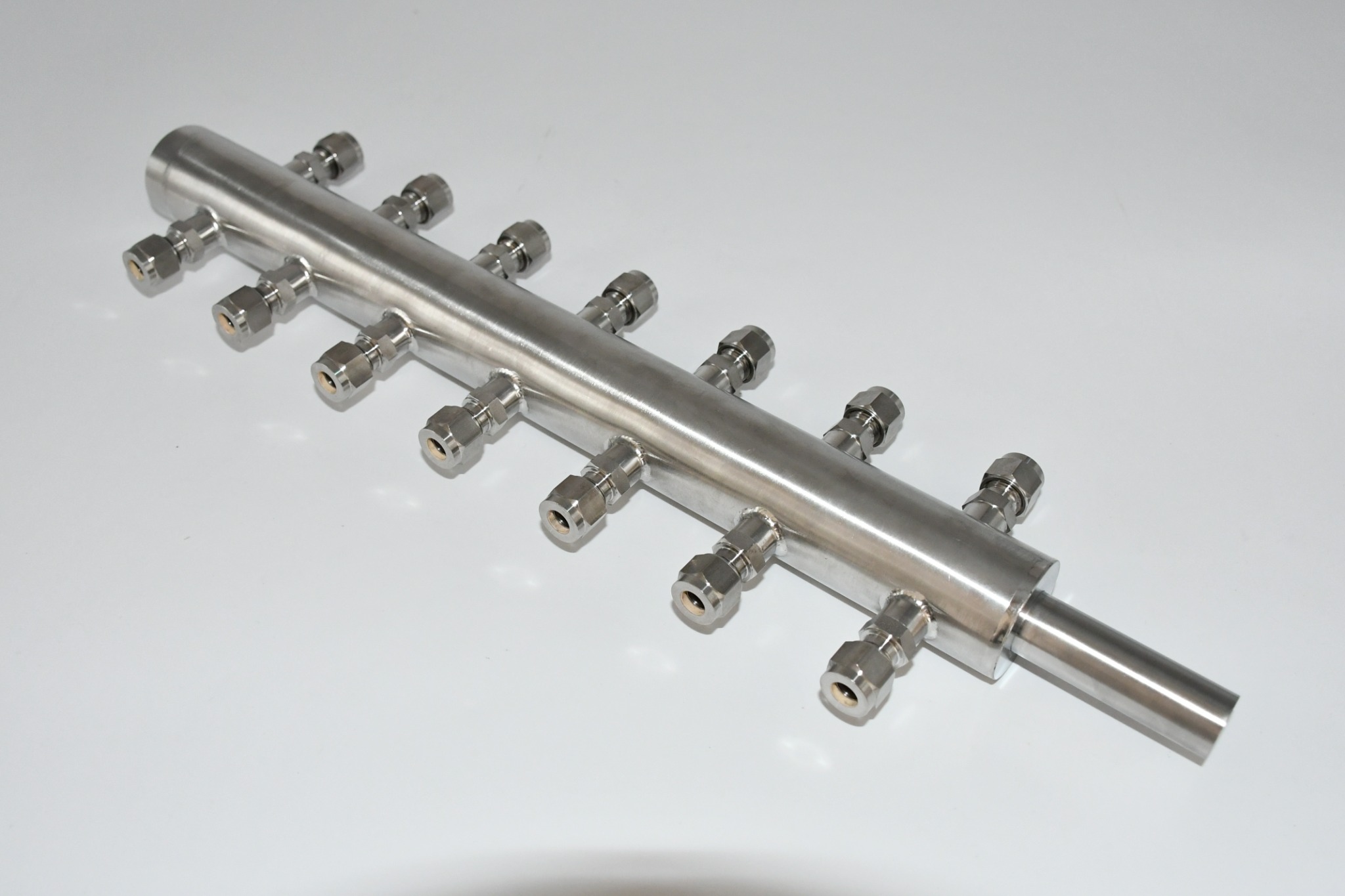
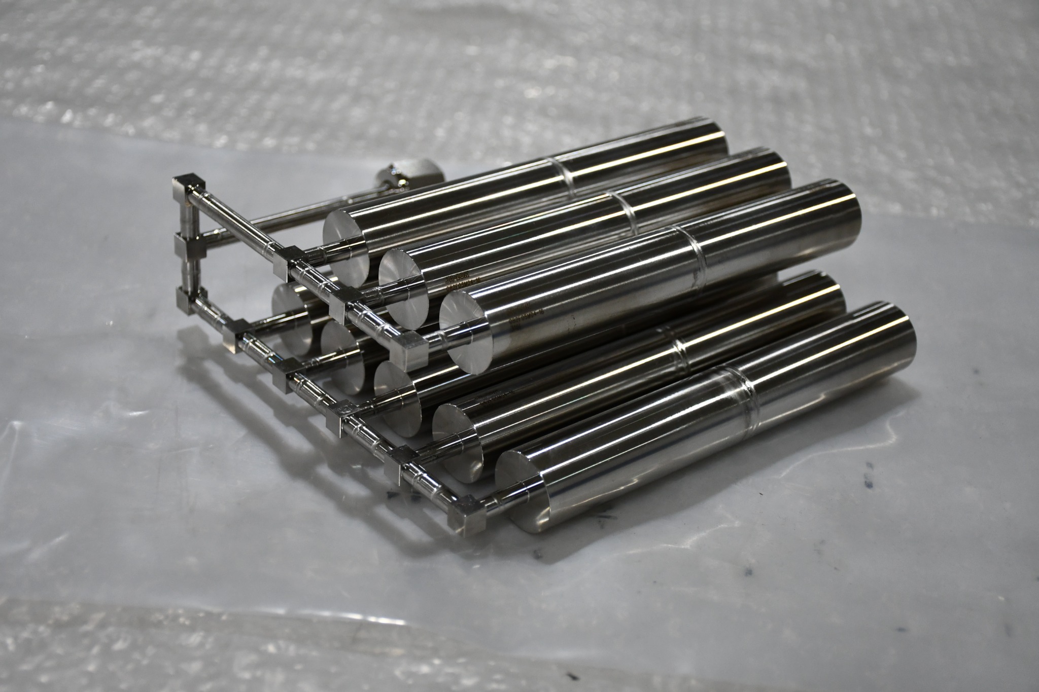
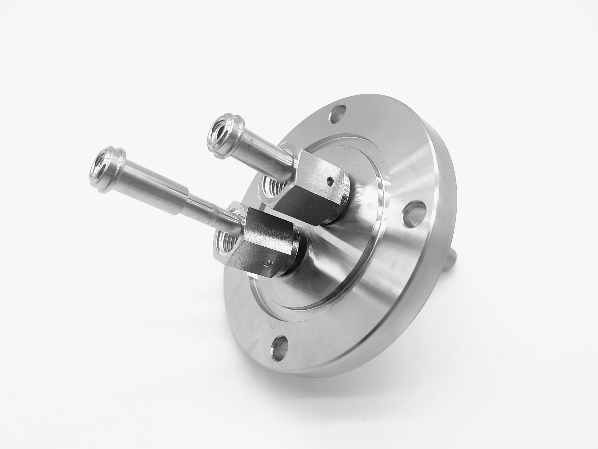
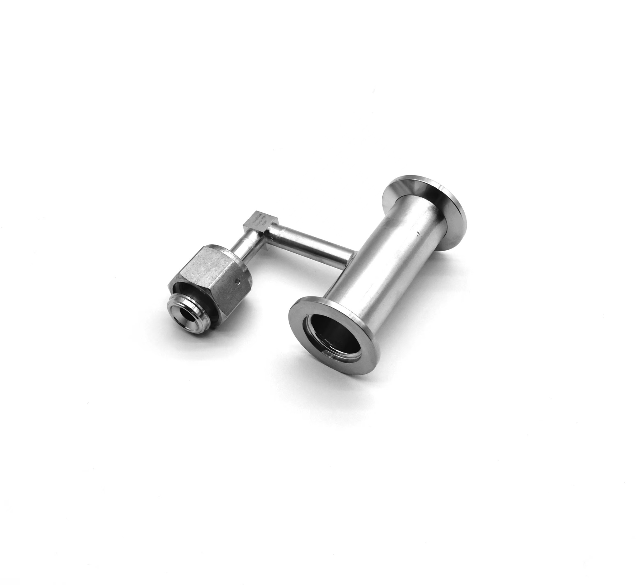
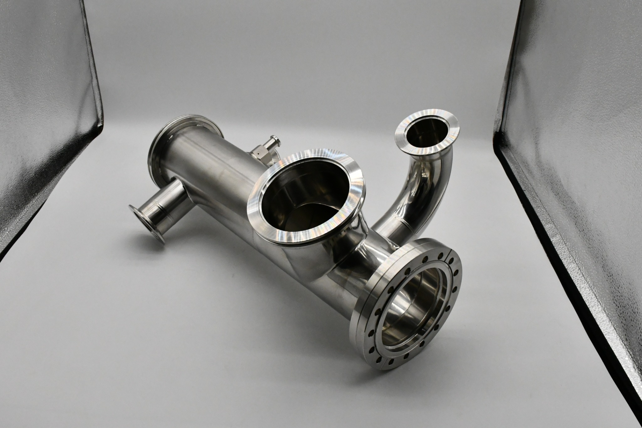
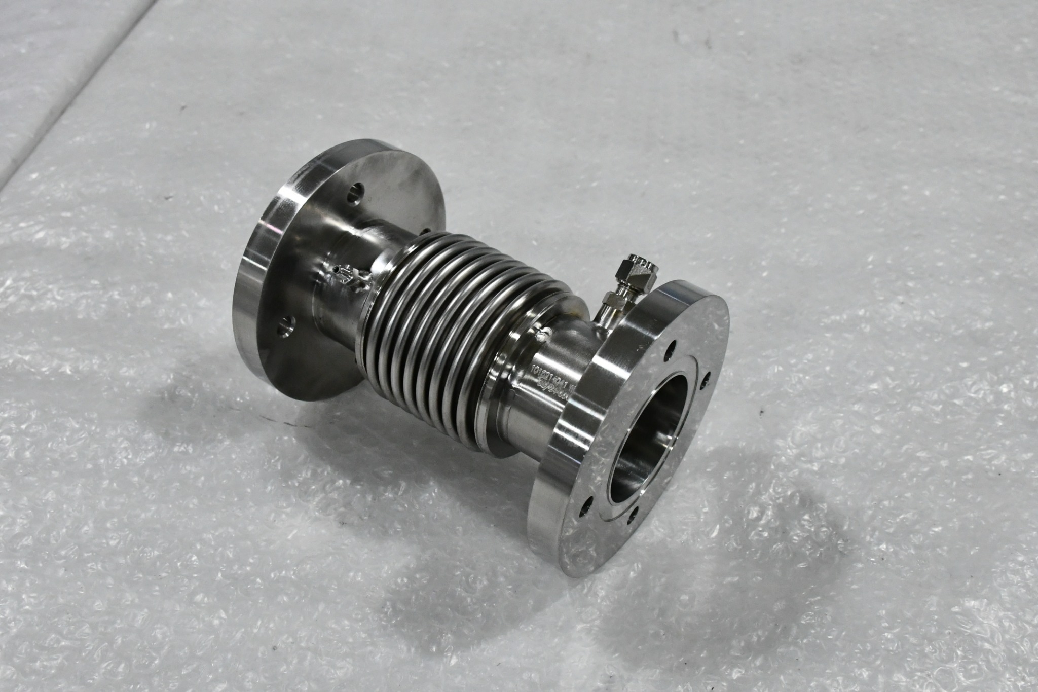
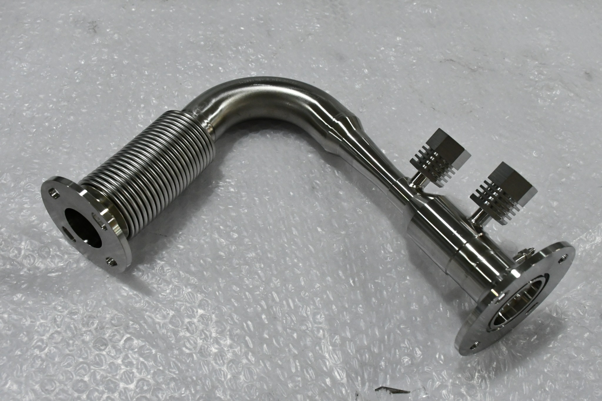
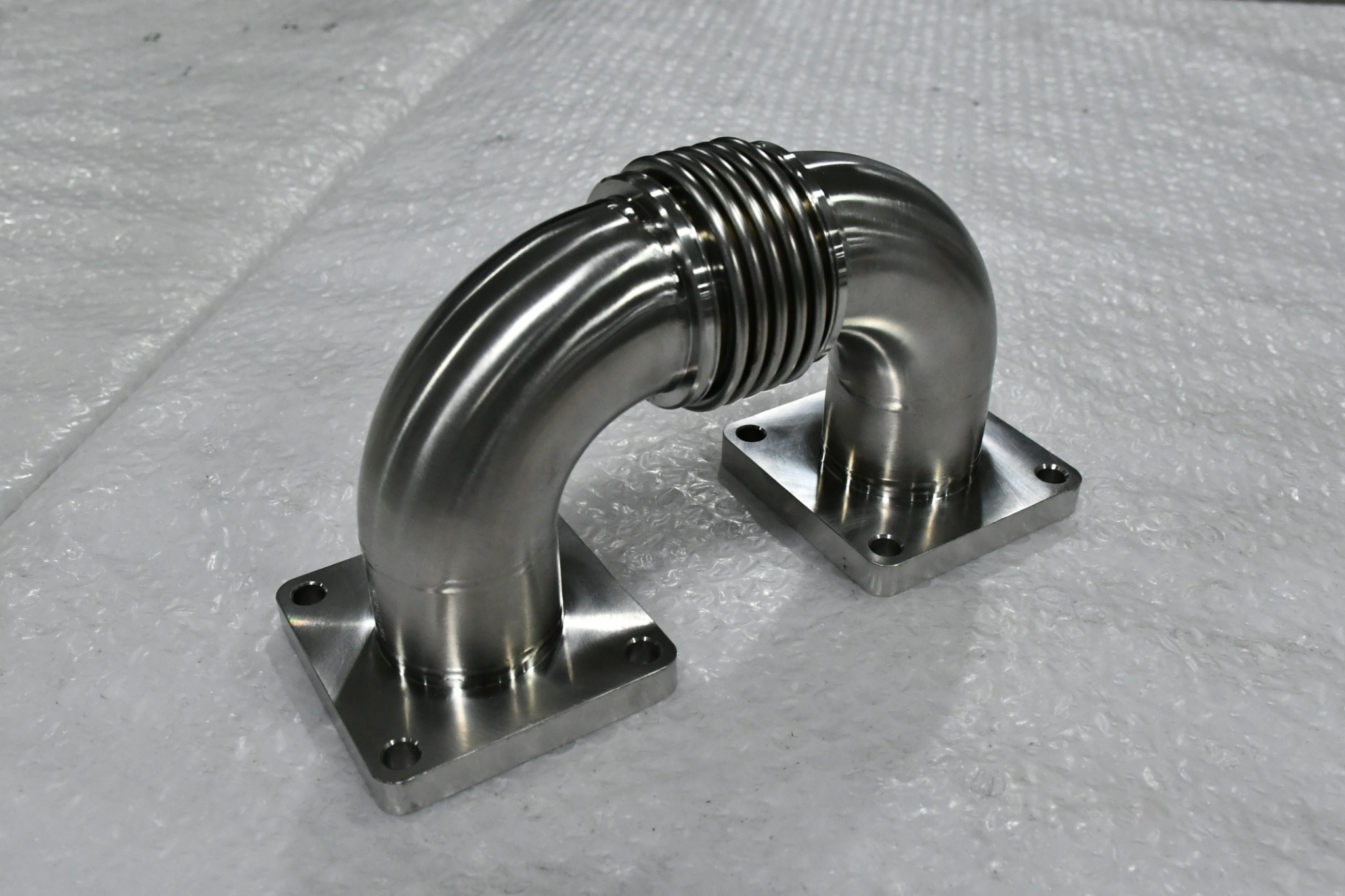
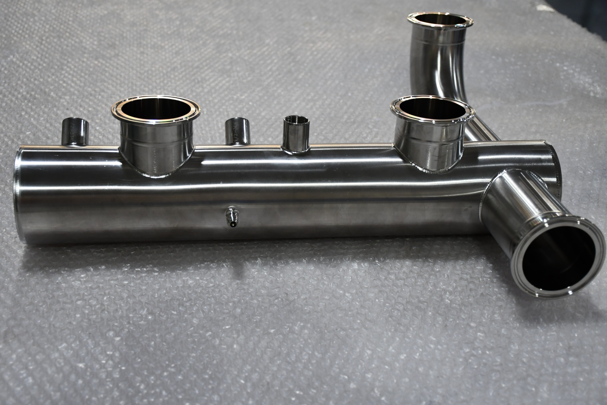
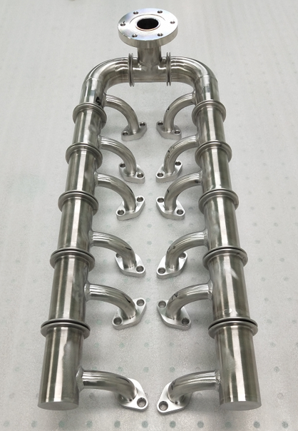
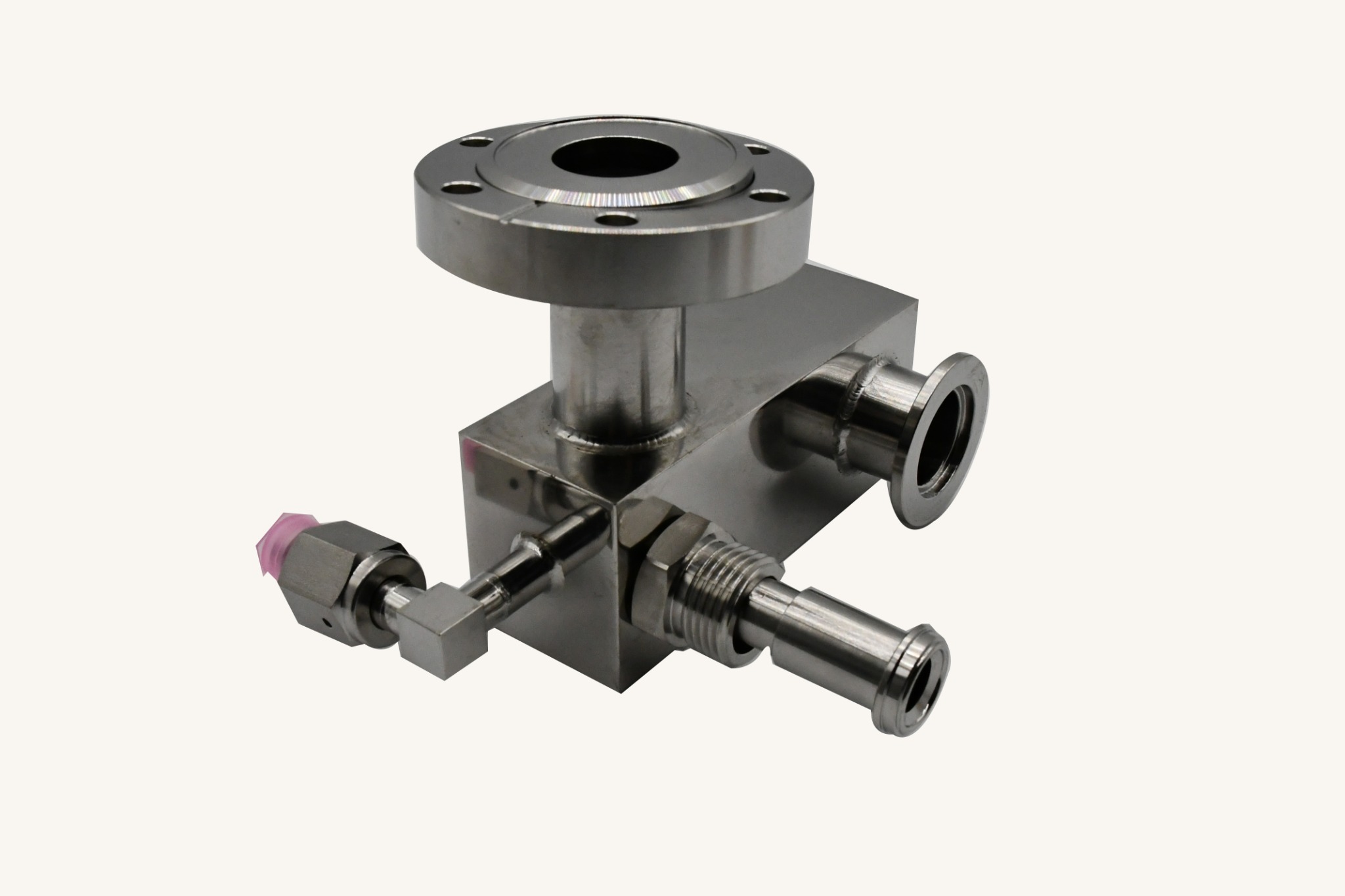
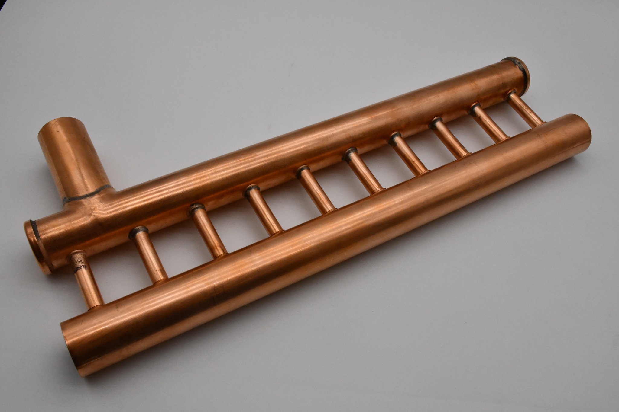
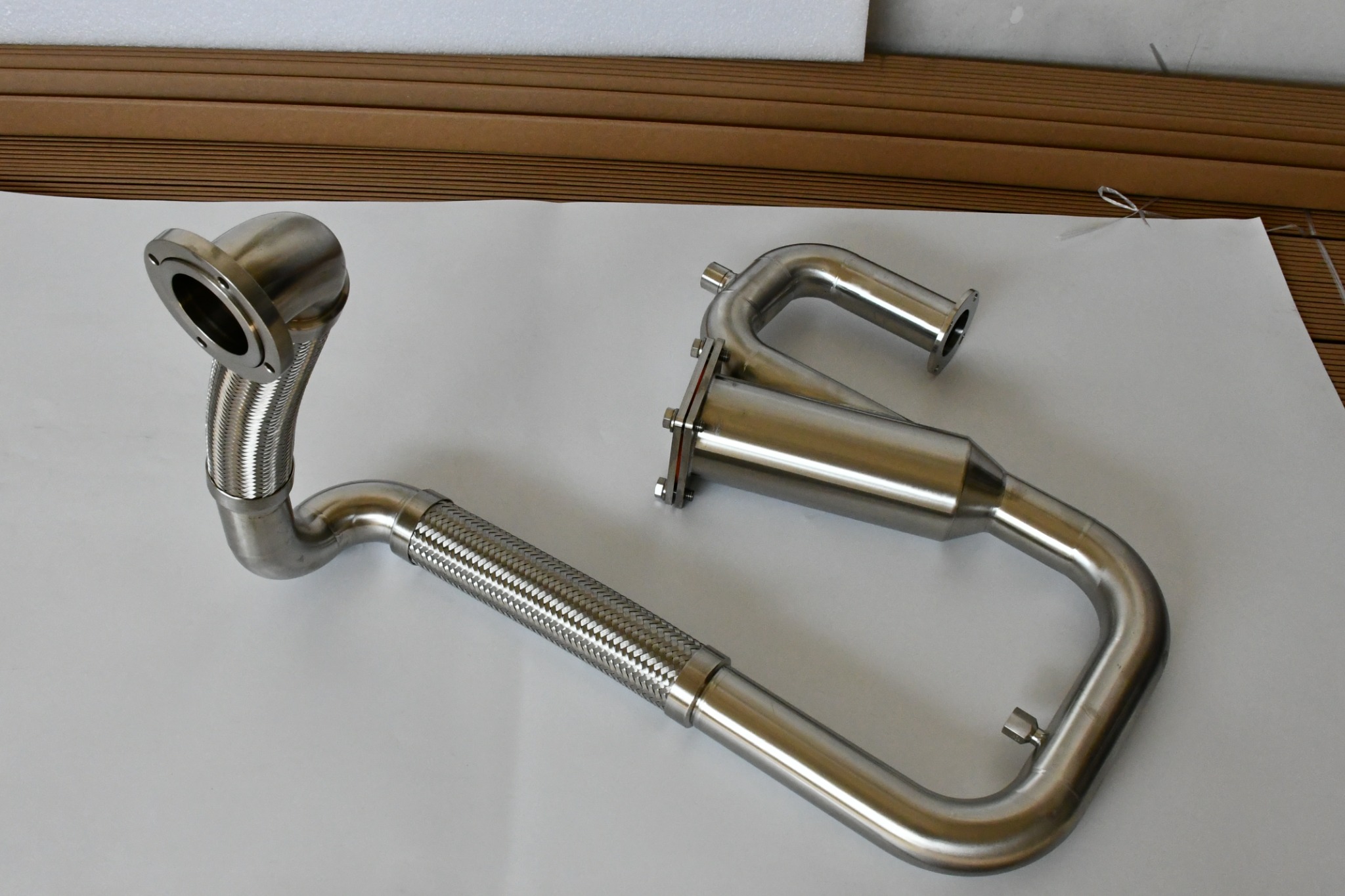
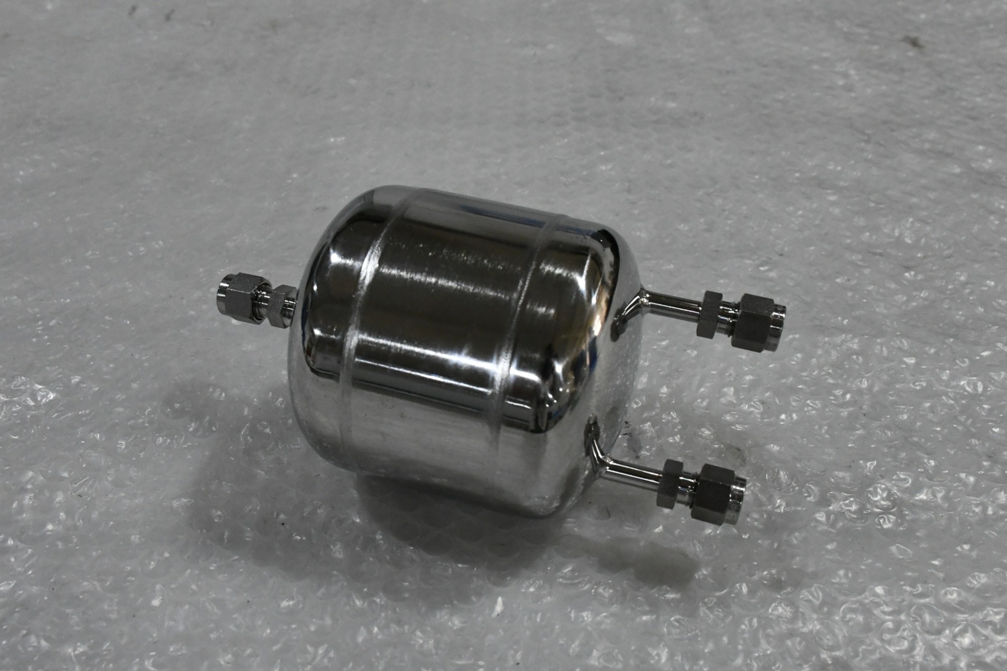
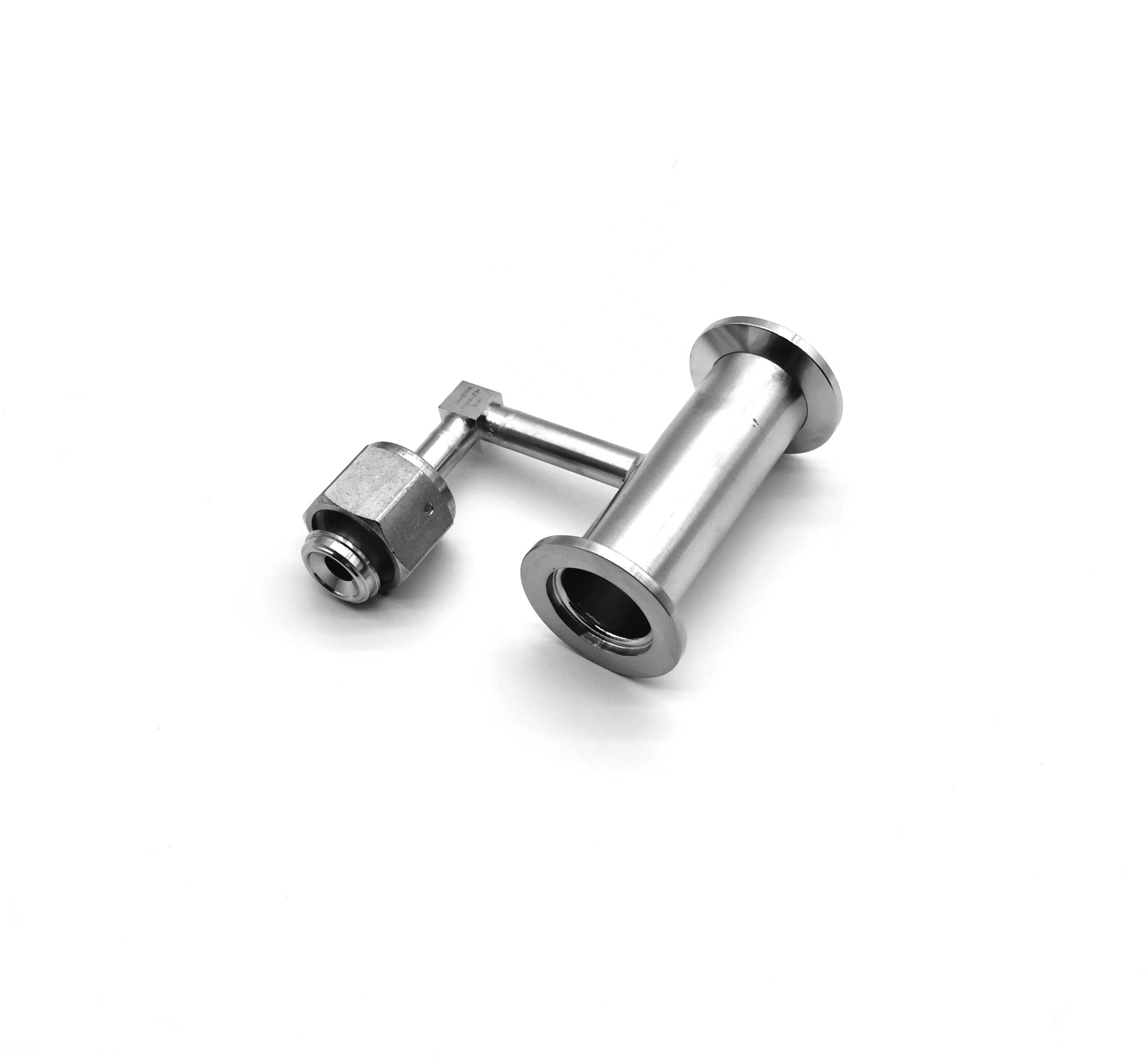
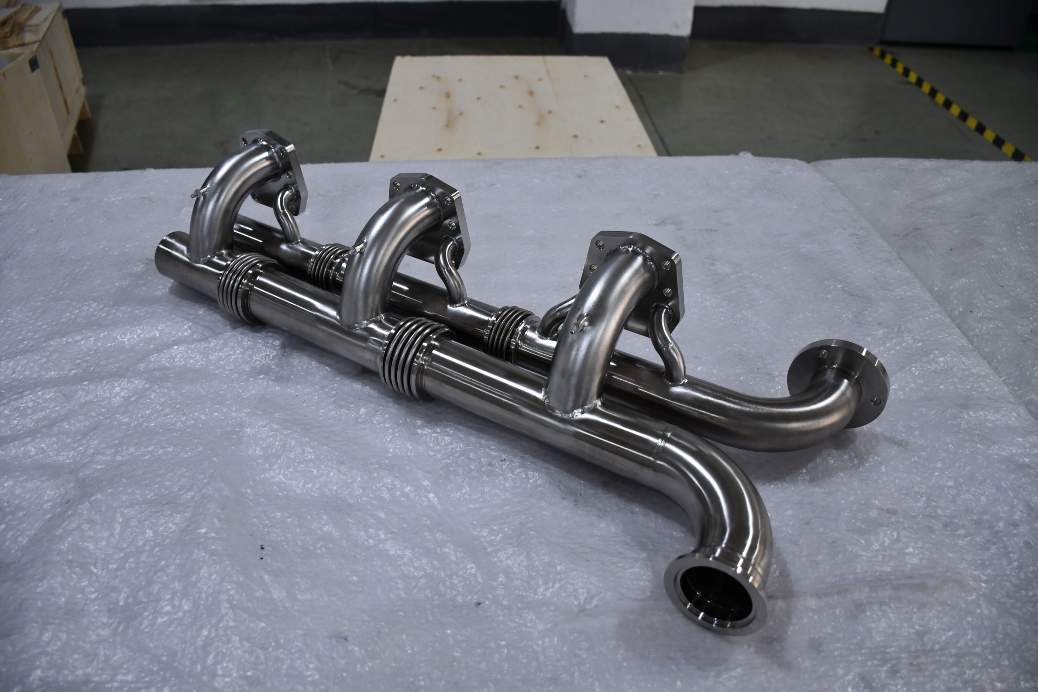
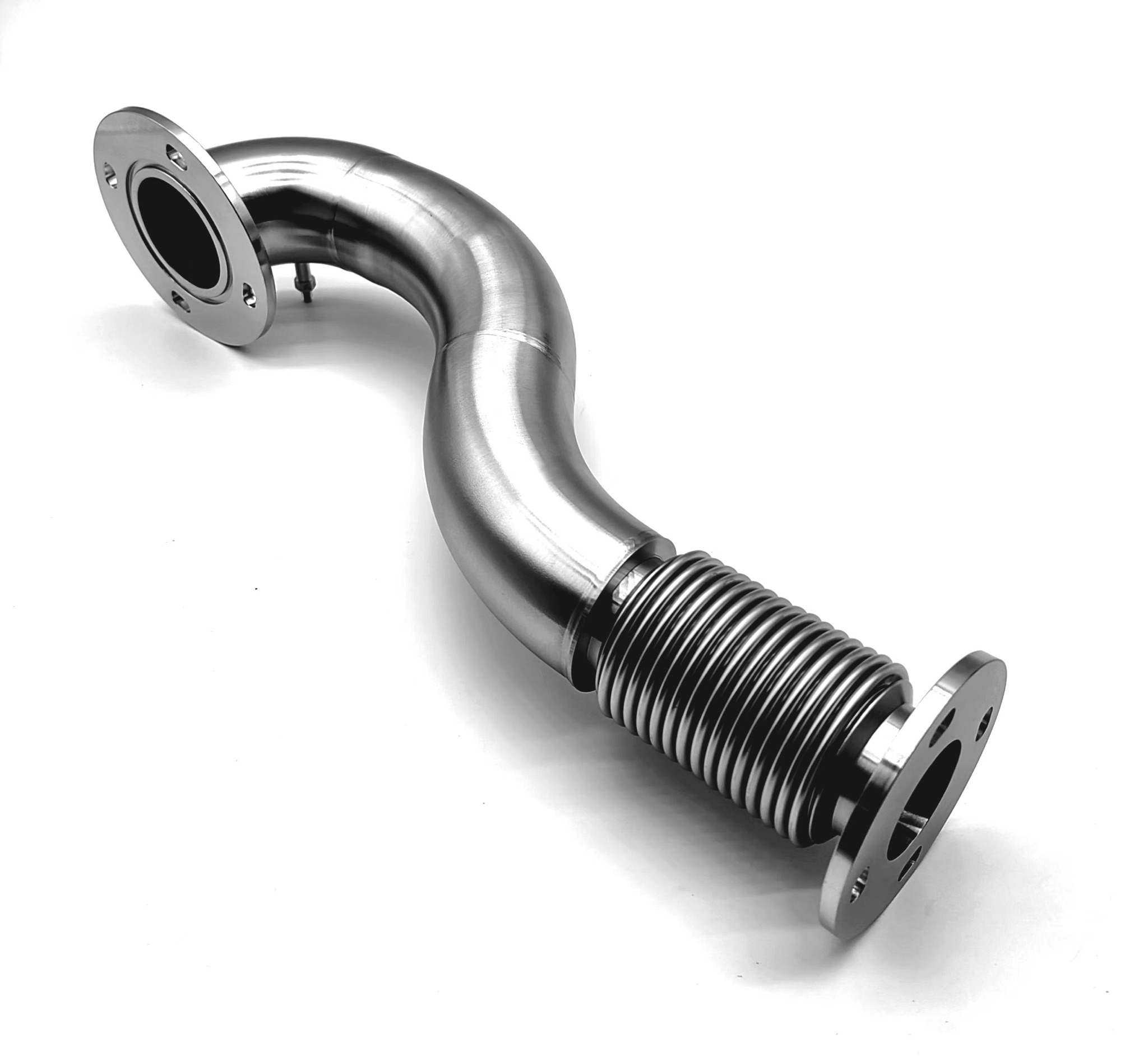
Explore vacuum cooling connection assemblies through the product photos below: flanged connections, bent tubing, bellows sections and multi-port welded manifolds.

  • Custom routing with flanged ends, branches and auxiliary connections
  • Assembly layouts combining formed tubing and selected bellows sections
  • Share your drawing, medium, operating conditions, connection dimensions and test requirements for product selection
Discuss vacuum cooling products →
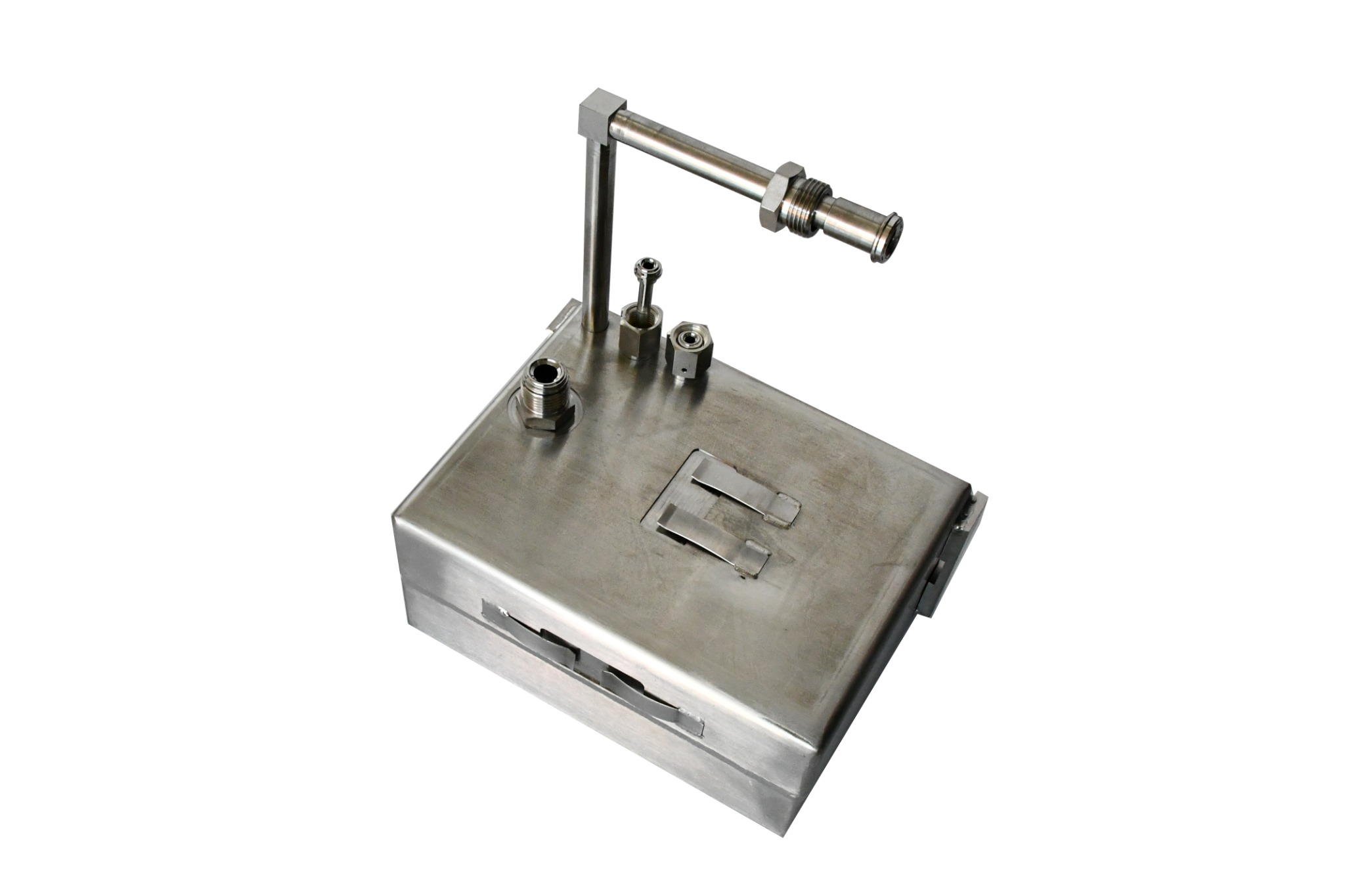
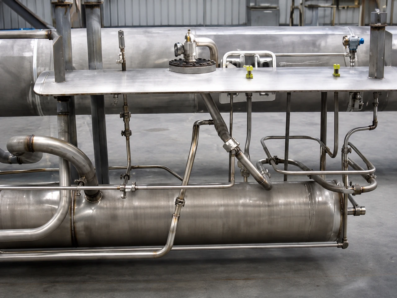
Multi-branch welded manifold

Click a photo to view it at full size. Product dimensions, materials and operating ratings are confirmed against the selected drawing.

03 / CUSTOM SPATIAL ROUTING

Freeform Bent & Welded Products

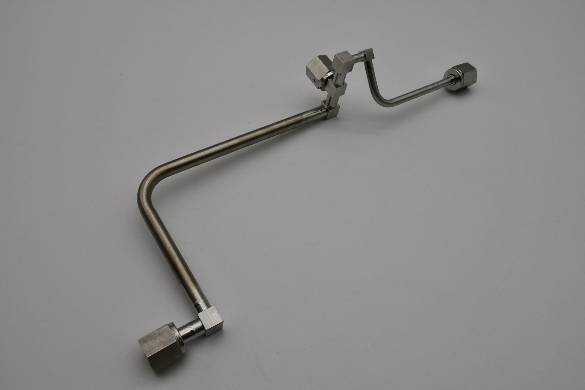
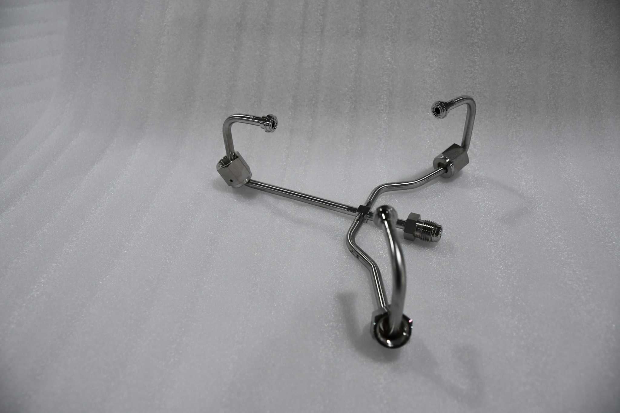
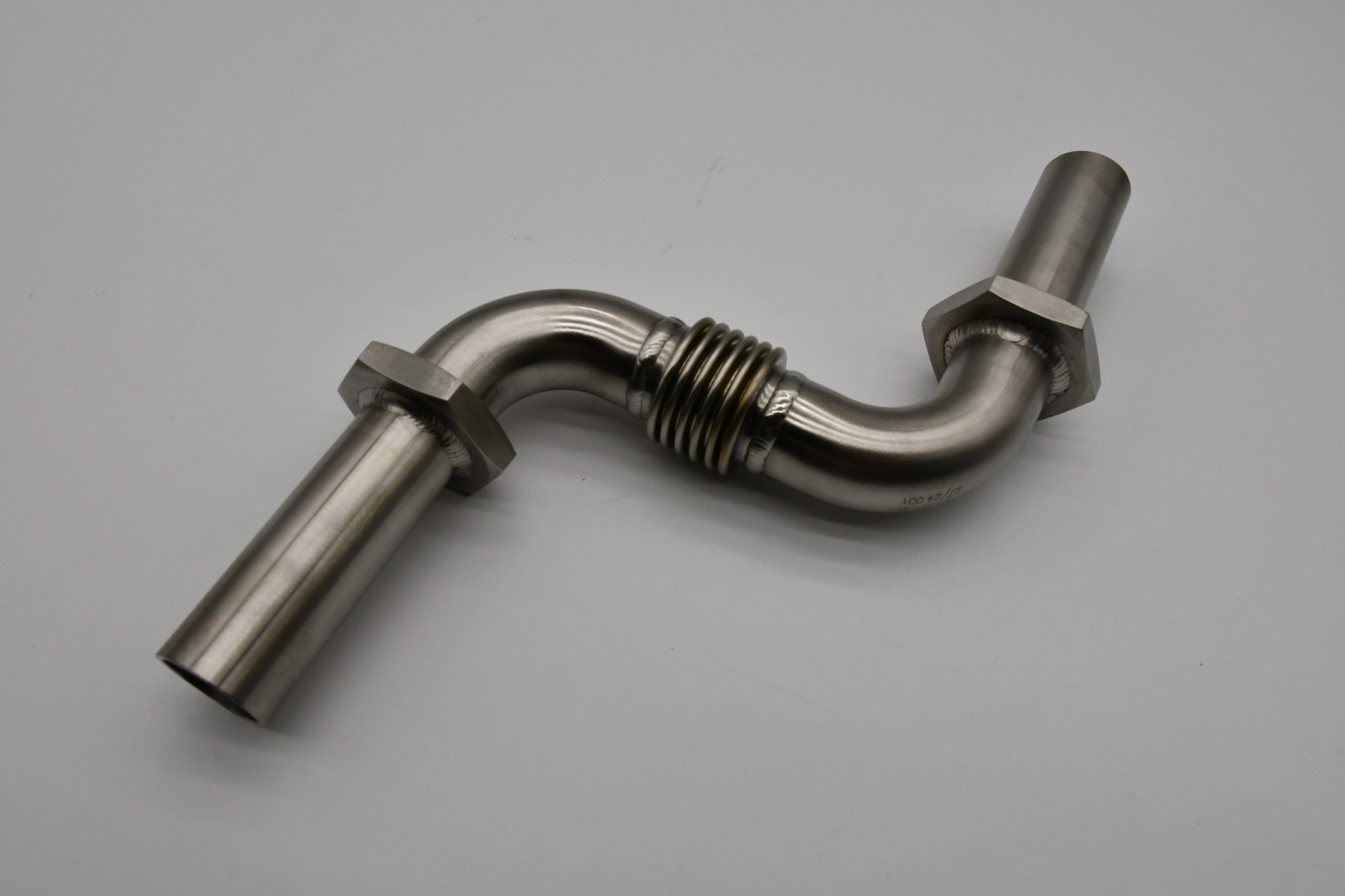
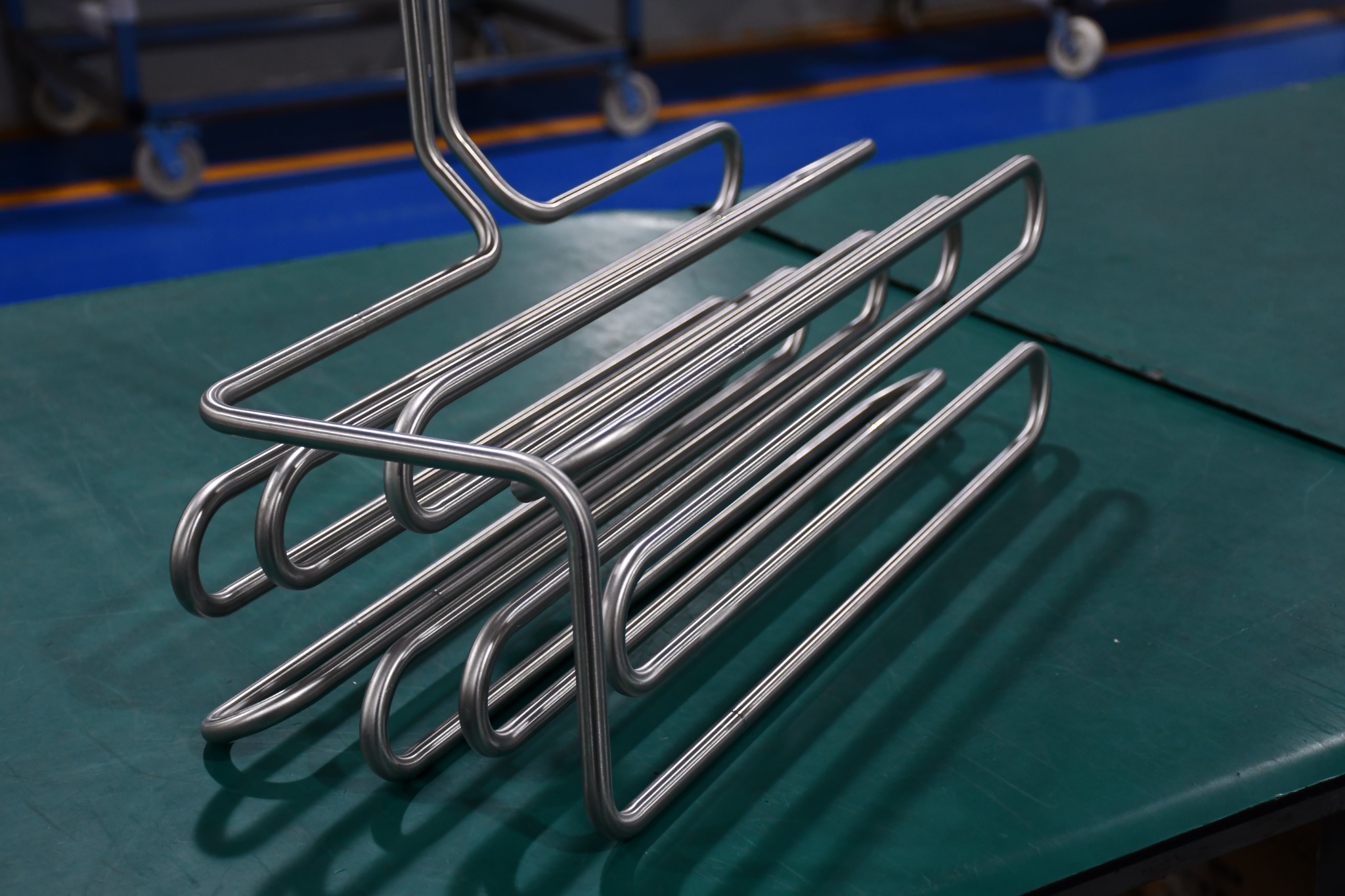
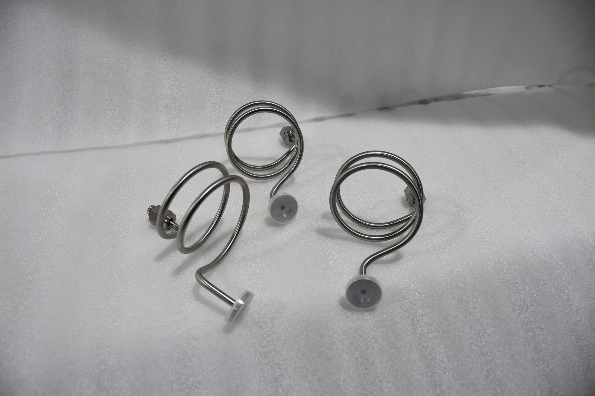
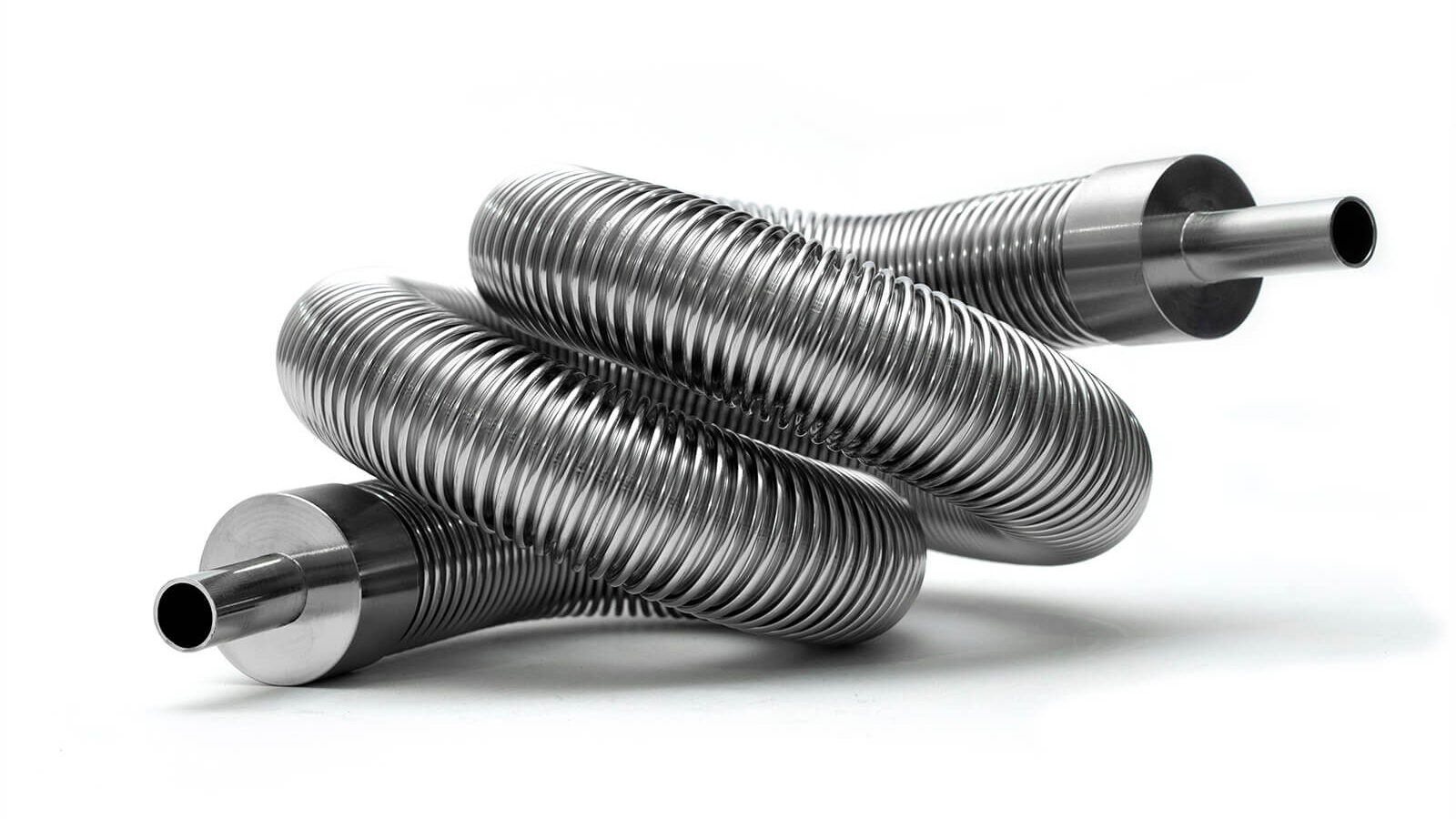
Custom-shaped tubes, manifolds and welded assemblies arranged around the available installation space. Explore coiled paths, return bends, branching layouts and combinations of rigid and flexible sections.

  • Define three-dimensional routing, bend radii, angles and end orientations
  • Combine branches, manifolds and selected flexible sections to suit the design
  • Share a drawing or 3D model, materials, tolerances and operating conditions
Discuss this product area →
Multi-plane formed tube layouts

Click a photo to view it at full size. Final specifications are confirmed against the selected drawing.
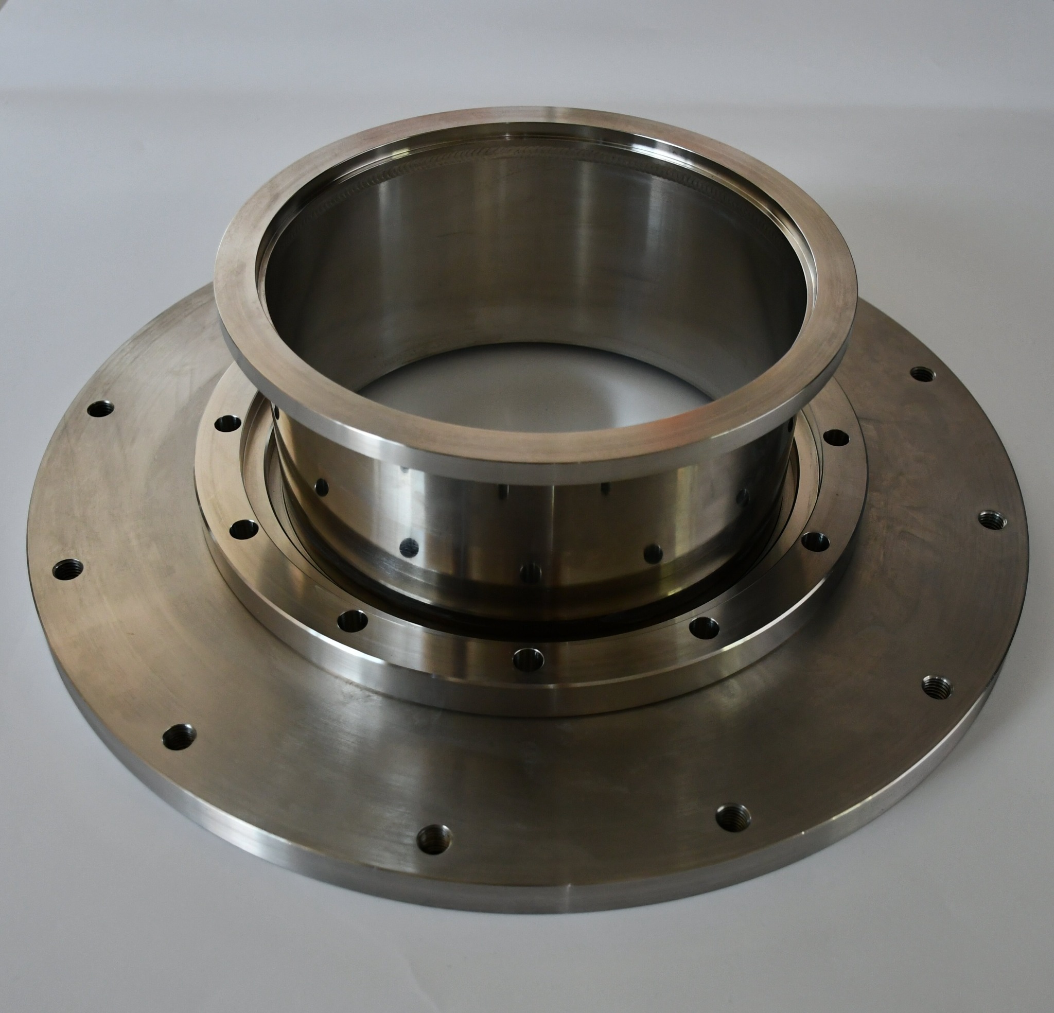
Product examples from the supplied brochure and vacuum cooling photos.

The three product areas use the supplied product photographs, grouped by product category. Final geometry, material, weld procedure and acceptance tests are defined for each project.

Supporting components & specifications

Hoses, bellows & connection references.

Explore existing connection families and dimensional references for component selection alongside a welded assembly.

KF Vacuum Hoses & Formed BellowsISO Clamp-Type Formed BellowsBolted-Flange Vacuum BellowsWeld-End Vacuum Bellows — VPSpecialty-Gas Flexible HosesSanitary Flexible HosesCustom Bellows AssembliesVacuum Flanges & Standard ComponentsCorrugated Tubing StockPrefabricated Vacuum Piping
KF hose and formed-bellows assemblies
KF hose and formed-bellows assemblies · Product illustration; refer to confirmed drawings for specifications.
01 / QUICK-CLAMP CONNECTIONS

KF Vacuum Hoses & Formed Bellows

Flexible vacuum connections with KF-style clamp ends. The catalogue includes conventional flexible tubes and thin-wall formed bellows in 304 and 316L stainless steel.

  • Flexible tubes accommodate bending, vibration, angular and lateral movement.
  • Formed bellows provide flexibility and axial movement within the specified design limits.
  • Select by connection dimensions, free length, bend radius and movement requirements.
Request this component →
KF flexible tubes — dimensional reference
ModelIDODABCWall thicknessMin. bend radius
F.KF1010.515.23012.2180.1530
F.KF1620.3293017.2180.270
F.KF2526354026.2180.290
F.KF4040525541.2180.25120
F.KF5054677552.2180.25140
F.KF6563808770.2220.25150
F.KF8078.510211483220.25220
F.KF100101126134102220.25280

Dimensions in mm unless stated otherwise. A, B, C, D, E and L are supplier drawing symbols; confirm the corresponding drawing before selection.

KF formed bellows — dimensional reference
ModelIDODABCWall thicknessMovement notation
B.KF162030.53017.2180.15± (E × 14%)
B.KF2525.3364026.2180.15± (E × 16%)
B.KF4039.5545541.212.70.15± (E × 22%)
B.KF5049.5657552.2150.15± (E × 23%)
B.KF6562.7828770.2150.15± (E × 26%)
B.KF8078.510211483220.2± (E × 26%)
B.KF100101126134102220.2± (E × 27.5%)

Dimensions in mm unless stated otherwise. A, B, C, D, E and L are supplier drawing symbols; confirm the corresponding drawing before selection. E denotes the free length in the source drawing; confirm permissible travel and fatigue conditions.

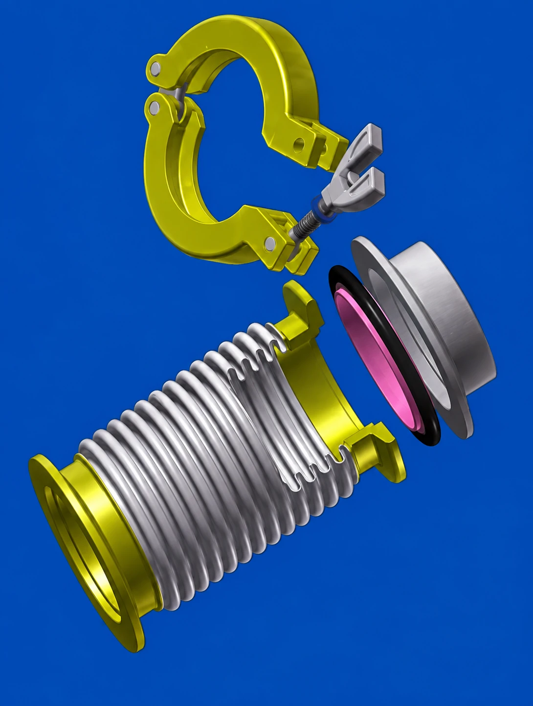
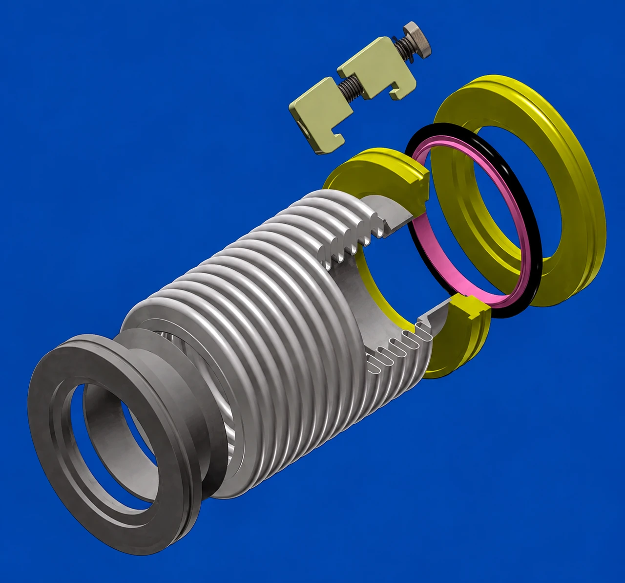
ISO clamp-type formed-bellows assembly
ISO clamp-type formed-bellows assembly · Product illustration; refer to confirmed drawings for specifications.
02 / CLAW-CLAMP FLANGE CONNECTIONS

ISO Clamp-Type Formed Bellows

Formed bellows with ISO clamp-type vacuum flange connections. The supplied catalogue identifies 304 and 316L for both bellows and flanges.

  • Catalogue model designations run from ISO-63 to ISO-320.
  • Confirm flange interface, free length and permissible motion.
  • Nominal designations are reproduced as printed, including ISO-150.
Request this component →
ISO formed bellows — dimensional reference
ModelIDODABCWall thickness
ISO-6362.7829570.2120.2
ISO-8078.510211083120.2
ISO-100101126130102120.2
ISO-125125153155127120.3
ISO-150149176.2180153120.25
ISO-200200240240213120.4
ISO-250250302290261120.4
ISO-320300351370318170.4

Dimensions in mm unless stated otherwise. A, B, C, D, E and L are supplier drawing symbols; confirm the corresponding drawing before selection. Source model labels are retained; flange compatibility must be checked against a drawing.
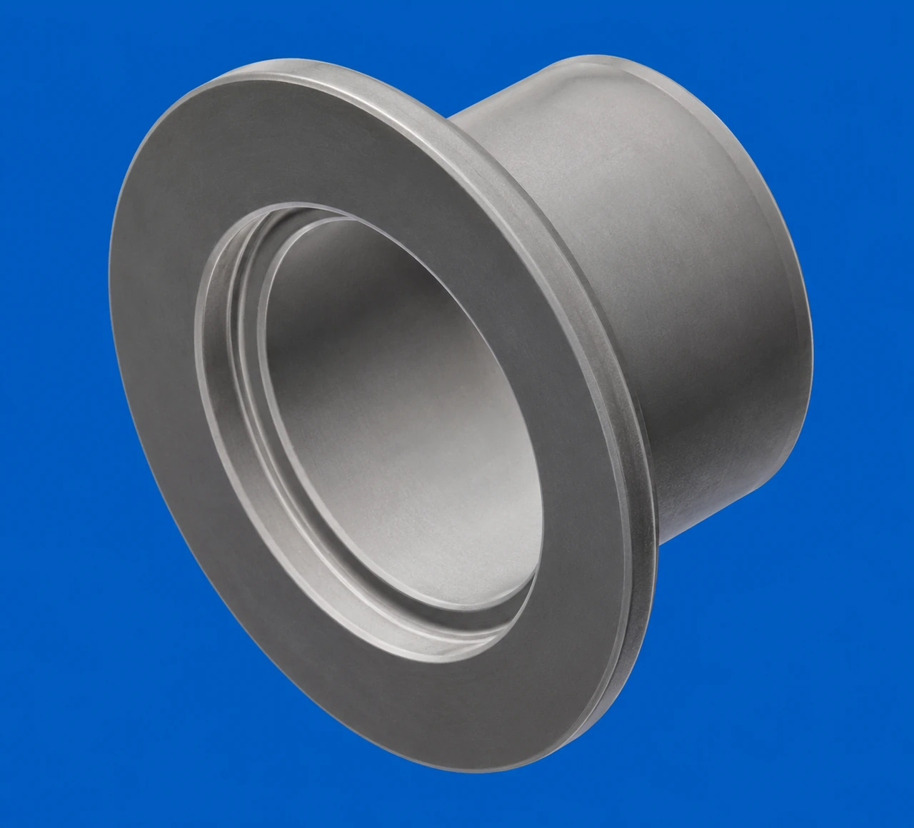
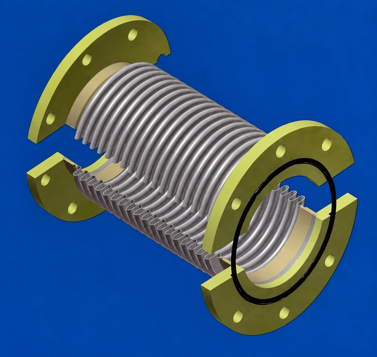
Bolted-flange vacuum bellows
Bolted-flange vacuum bellows · Product illustration; refer to confirmed drawings for specifications.
03 / FIXED BOLT-HOLE INTERFACES

Bolted-Flange Vacuum Bellows

Vacuum bellows with bolted flange connections. The catalogue lists 304 flange material and 304 or 316L bellows material.

  • Two dimensional series are shown: GB/T 6070 and VG.VF-JIS.
  • Specify the bolt circle, hole count, hole diameter and sealing interface.
  • A bolted flange connection is not a threaded tube-end fitting.
Request this component →
Bolted flanges — source series GB/T 6070
SizeIDODAPCDCWall thicknessHoles (N)Hole dia. (D)
8078.5102145125120.289
100101126165145120.289
160149.3176.2225200160.25811
200200240285260160.41211
250250302335310160.41211
320300351425395200.41214

Dimensions in mm unless stated otherwise. A, B, C, D, E and L are supplier drawing symbols; confirm the corresponding drawing before selection.

Bolted flanges — source series VG.VF-JIS
SizeIDODAPCDCWall thicknessHoles (N)Hole dia. (D)
4039.55410585100.15410
5049.565120100100.15410
6562.782145120100.2412
8078.5102160135120.2412
100101126185160120.2812

Dimensions in mm unless stated otherwise. A, B, C, D, E and L are supplier drawing symbols; confirm the corresponding drawing before selection. Standard editions and certification have not been provided.

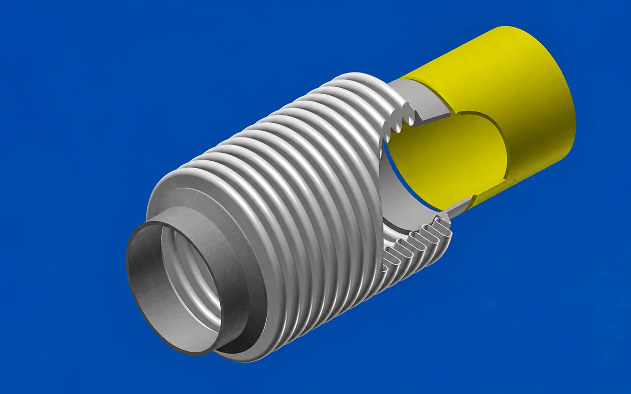
VP weld-end vacuum bellows
VP weld-end vacuum bellows · Product illustration; refer to confirmed drawings for specifications.
04 / WELD-IN PIPING CONNECTIONS

Weld-End Vacuum Bellows — VP

Flexible tubes and formed bellows with weld ends for integration into vacuum piping. The VP catalogue page identifies 304 and 316L for end connections and bellows.

  • Select end dimensions A, B and C against the supplier drawing.
  • Define installed length, alignment and weld procedure.
  • The catalogue describes vacuum inside and atmospheric pressure outside.
Request this component →
VP weld ends — dimensional reference
ABC
6430
6.35430
8630
9.527.5230
10830
129.430
12.79.430
19.0515.7540
25.422.140
38.135.140
42.737.120
50.847.821
60.557.220
63.560.220
76.272.220
898120
101.697.620
10810020
13312920
15915120
21920925
27526325
35534325

Dimensions in mm unless stated otherwise. A, B, C, D, E and L are supplier drawing symbols; confirm the corresponding drawing before selection.

Specialty-gas flexible hose
Specialty-gas flexible hose · Product illustration; refer to confirmed drawings for specifications.
05 / 316L CONNECTIONS AND BELLOWS

Specialty-Gas Flexible Hoses

Flexible hose configurations for specialty-gas piping, including compression-fitting connections. The catalogue specifies 316L for the connections and corrugated tube.

  • Listed connection sizes: 1/4 in, 3/8 in, 1/2 in and 3/4 in.
  • Discuss gas compatibility, cleanliness and connection geometry.
  • Confirm cleaning, packaging and qualification requirements for the actual application.
Request this component →
Specialty-gas hose — listed connection sizes
Size (in)Catalogue equivalent (mm)
1/46.35
3/89.52
1/212.7
3/419.05

Dimensions in mm unless stated otherwise. A, B, C, D, E and L are supplier drawing symbols; confirm the corresponding drawing before selection.

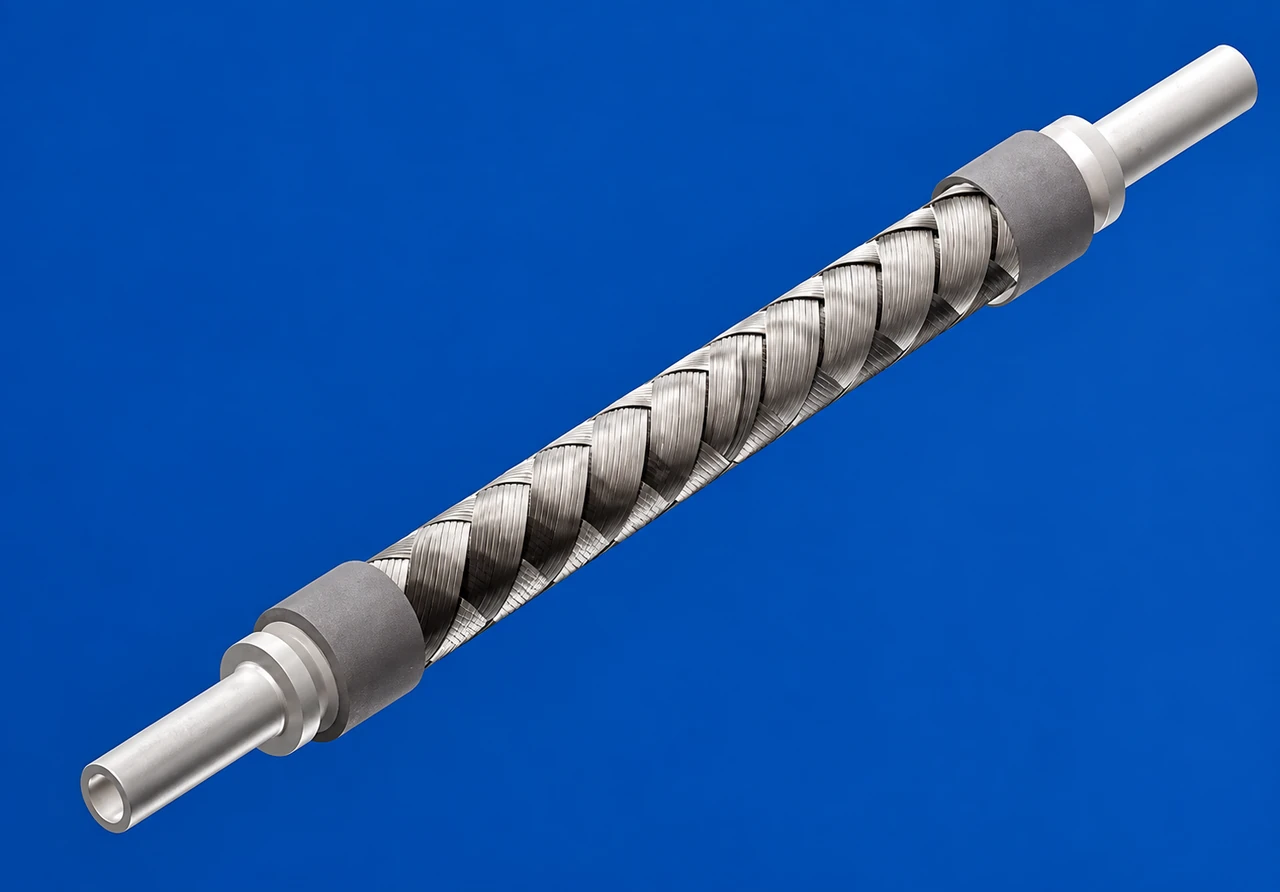
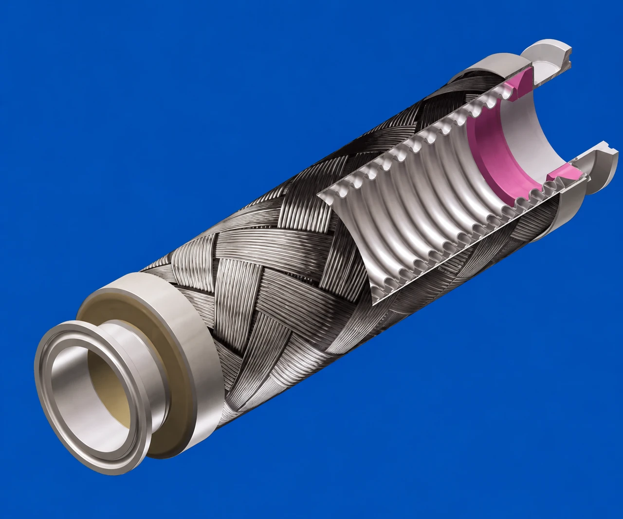
Braided sanitary flexible hose
Braided sanitary flexible hose · Product illustration; refer to confirmed drawings for specifications.
06 / FOOD-PROCESSING APPLICATIONS

Sanitary Flexible Hoses

The supplier catalogue includes braided corrugated hoses intended for sanitary food-processing applications.

  • Listed sizes: 1/2 in, 1 in, 1.5 in and 2 in.
  • Confirm contact materials, weld finish and cleaning requirements.
  • No sanitary certification is implied by the product-category name.
Request this component →
Sanitary hose — listed sizes
Size (in)Catalogue equivalent (mm)
1/212.7
125.4
1.538.1
250.8

Dimensions in mm unless stated otherwise. A, B, C, D, E and L are supplier drawing symbols; confirm the corresponding drawing before selection.

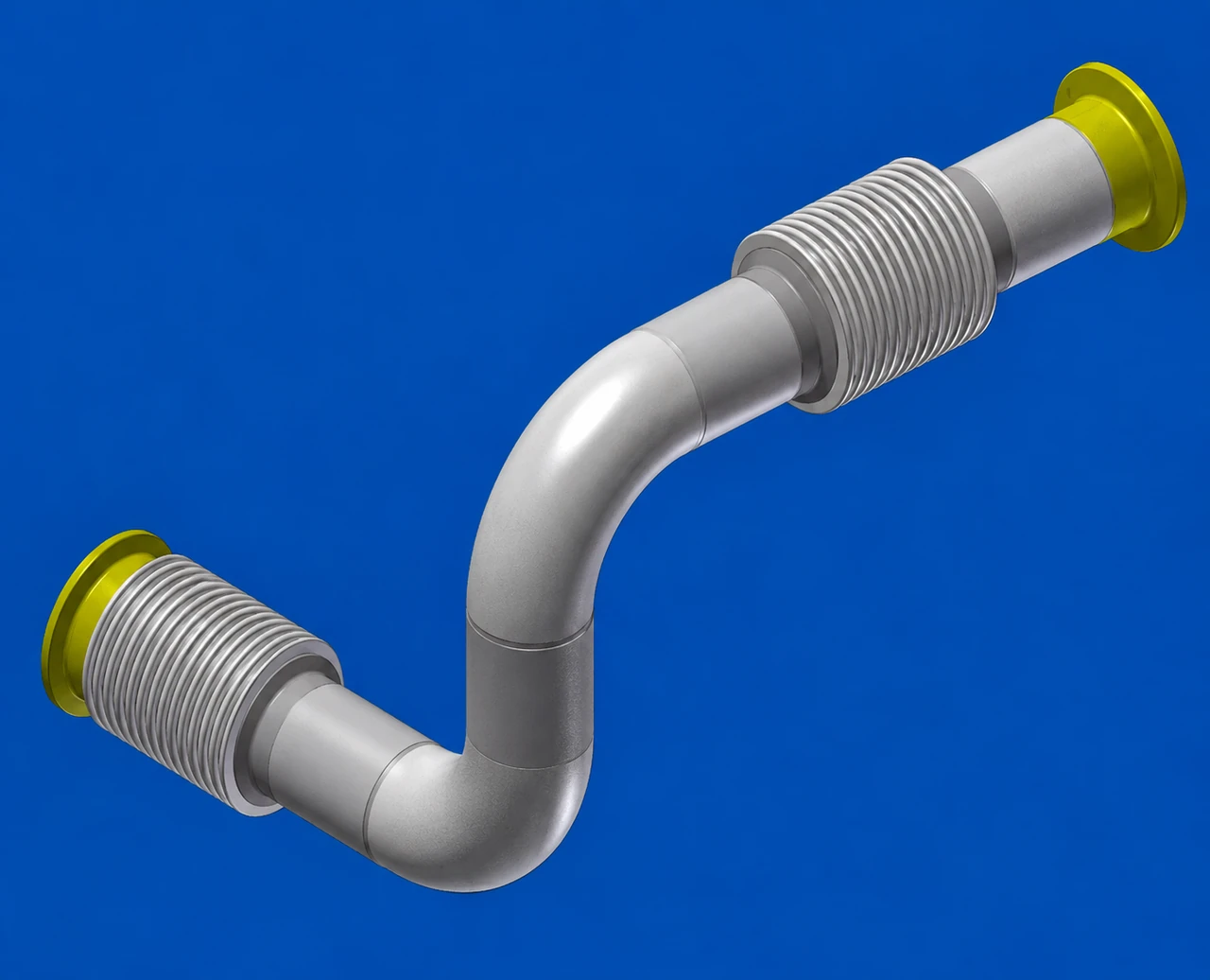
Custom bellows and bent-pipe assembly
Custom bellows and bent-pipe assembly · Product illustration; refer to confirmed drawings for specifications.
07 / PROJECT-SPECIFIC GEOMETRY

Custom Bellows Assemblies

Non-standard bellows assemblies combine flexible sections, bends and different end connections. Dimensions are determined by the project requirements.

  • Share an engineering drawing, installed envelope and connection details.
  • Define media, vacuum or pressure conditions, temperature and movement.
  • Mixed-flange and bent-pipe configurations require drawing review.
Request this component →
Vacuum flange connection component
Vacuum flange connection component · Product illustration; refer to confirmed drawings for specifications.
08 / CONNECTION-SYSTEM ACCESSORIES

Vacuum Flanges & Standard Components

The catalogue shows flanges, centering components, clamps, blanking components, elbows and tees for vacuum piping.

  • 304 and 316L are identified in the supplier flange discussion.
  • Select flange series, dimensions and sealing components together.
  • Supplier workshop and machining photographs are not AT Merchant Solutions facilities.
Request this component →
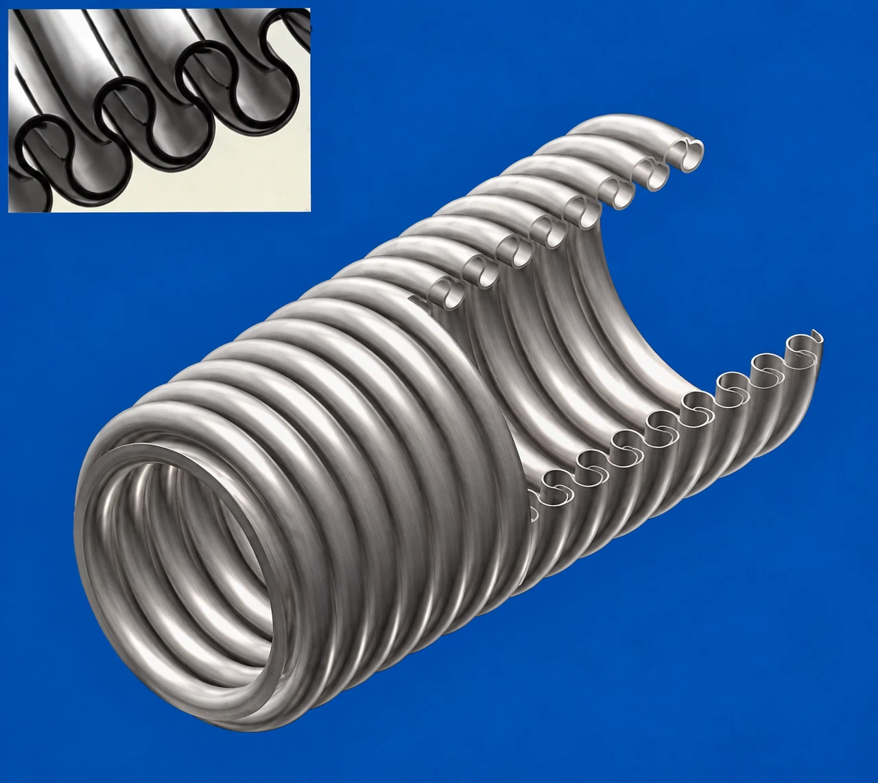
Corrugated tubing profile
Corrugated tubing profile · Product illustration; refer to confirmed drawings for specifications.
09 / FOR HOSE AND BELLOWS FABRICATION

Corrugated Tubing Stock

Vacuum corrugated tubing is described as precision stainless strip welded into thin-wall tube and then hydraulically formed.

  • The catalogue shows flexible-tube and formed-bellows profiles.
  • Stock designations cover 6 through 320, with several alternate profiles.
  • Confirm the profile, material grade and downstream fabrication requirements.
Request this component →
Corrugated tubing stock — dimensional reference
Model / sizeIDODWall thickness
669.50.15
87.8110.15
1010.515.20.15
1515200.2
2020.5290.2
20-120300.15
2525.4360.15
25-126.2360.2
4039.5540.15
40-140520.25
5049.5650.15
50-154670.25
6562.7820.25
65-162.5820.2
8078.51020.2
80-1781020.25
1001011260.2
100-1100.71260.25
1251251530.3
150149.3176.20.25
150-1149176.20.4
2002002400.4
2502503020.4
3203003510.4

Dimensions in mm unless stated otherwise. A, B, C, D, E and L are supplier drawing symbols; confirm the corresponding drawing before selection.

Supplier example of prefabricated vacuum piping
Supplier example of prefabricated vacuum piping · Product illustration; refer to confirmed drawings for specifications.
10 / DRAWING-BASED PIPING ASSEMBLIES

Prefabricated Vacuum Piping

The source includes examples of small vacuum-system piping assemblies, stainless tube preparation and precision TIG welding.

  • Use drawings to define routing, end connections and installation clearances.
  • Specify inspection, leak testing, cleanliness and packaging requirements.
  • Fabrication scope and supplier capabilities require project confirmation.
Request this component →

Technical notes from the supplied catalogue

The KF, ISO, bolted-flange and VP pages describe internal vacuum and external atmosphere. Their temperature notation is “below 250°”; confirm the temperature unit, seal material and actual assembly rating before use.

The KF page lists a leak-rate notation of < 5 × 10⁻⁹ Pa·m³/s. Test method, conditions and configuration were not supplied, so this is a catalogue reference rather than a verified acceptance guarantee.

Dimensions are transcribed from the supplied Chinese catalogue photographs. Some descriptive text is cropped at the page edge; incomplete claims have been omitted. Lengths, tolerances, pressure ratings, cycle life, certifications and current availability require a confirmed product drawing or specification.

Applications

Vacuum infrastructure for demanding processes.

Semiconductor & display equipment

Vacuum-system connections and flexible sections for semiconductor production, display manufacturing and precision vacuum equipment.

Exhaust & analytical systems

Connection requirements in exhaust assemblies, analytical instruments and other vacuum installations.

Research & industrial systems

The source also lists particle accelerators, fusion research, nuclear-energy facilities, petrochemical and building applications. Suitability needs application review.

Additional catalogue category: communications waveguide bellows

The supplied catalogue also shows rectangular brass bellows for communications waveguides, described as hydraulically formed. These are a separate electrical waveguide component family; dimensions and detailed text are incomplete in the supplied photograph.

Let’s discuss your next project.

Share your application, drawings and technical requirements.

Discuss your project ↗